Advertisement
Quick Links
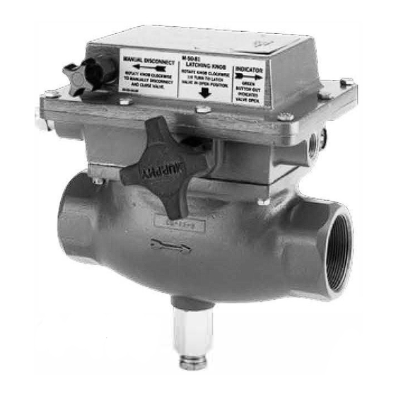
M2582, M5081, and M5180 Series
Electromechanical and Pneumatic, Fuel Gas Shut
off Valves Installation and Operation Instructions
Please read the following instructions before installing. A visual inspection of this product for damage during shipping is
recommended before mounting. It is your responsibility to have a qualified person install the unit and make sure installation
conforms with NEC and local codes.
M2582 and M5081 Series
Tripping Power From Engine Ignition System or Battery
(Models available for magneto, CD ignition or 12/24 V battery)
These fuel hut-off valves are semi-automatic device for shutdown
of natural gas fueled engines. The standard valve opens by manual
operation of the reset handle. A latch in the upper body of the valve
will set and hold the valve open. At this point no electric power is used.
The electromagnetic coil is de-energized, the snap-switch(es) is SET.
If a SWTCHGAGE' contact closes, a circuit is completed from power
through the nap-switch and coil. Now energized, the electromagnet
trips the latch, (latch can be tripped manually), the valve clo es, and the
snap-switch resets. Power switches from the coil circuit to your choice
of an open line, an electrical ground, or an alarm. After tripping, the
vent seal opens, and on the MS0 models, the open/close indicator (green
button) retracts to indicate that the valve is closed.
Valve body is sandcast aluminum. Optional cast steel for MS08 I models.
M2582-P and M5180-P
MURPHY-NUMATIC'" Pneumatic Version for Pressure
The M2582-P and MS 180 pneumatically controlled v alve can operate
from pres ure, and are designed to open and close automatically or semi
automatically (the supply can be air, oil or gas).
NOTE: If using oil as a pressure source, use a lightweight oil.
The e valve will open on ri ing control pres ure and close on
decreasing control pressure. M2582-P and MS 180-P automatically open
at 2 psi (14 kPa) [0.14 bar] and fully open at 3 psi (21 kPa) [0.21 bar].
All models include a built-in lever to aid in opening the valve manually.
The M2582-P can be manually opened against inlet pressure of 80 psi
(552 kPa) [5.52 bar]. The MS 180-P valve can be opened against inlet
pres ure of I 00 p i (689 kPa) [6.89 bar].
Standard models include an escape vent for gas trapped forward in the
line after shut-off.
GENERAL INFORMATION
M5081FS
Normally Energized Circuit
The M508 IFS i manually opened, electrically latched open and tripped
by interrupting the coil power circuit.
Magnetic Switch Adapter
As ignition ystem wear from u age, their power output becomes less
and le . lgn it ion may not have the capacity to reliably trip the Fuel
Valve. Therefore, the use of a Magnetic Switch Adapter for CD ignition
systems is recommended. The Magnetic Switch Adapter is a device that
stores energy from the CD ignition to trip the Fuel Valve. Three models
are available:
65700053 (was 65020126): For use with negative ground ignitions
up to 240 VDC.
65700054 (was 65020127): For use with positive ground ignitions up
to450 VDC.
65700055 (was 65020155): For use with negative ground ignitions
up to 450 VDC.
100 ohm, 2 watt Resistor
For Capacitor Discharge Ignitions that are specified to be grounded when
the valve closes and a Magnetic Switch Adapter is in use. The resistor
must be connected in the system to prevent damage to the snap-switches
in the fuel shut-off valve (see typical wiring diagrams).
Diode Package
The Murphy diode package (65010065) is designed to allow the fuel shut
off valve to be used with dual Magneto Ignition systems.
NOTE: All aluminum versions of the M508J Series Fuel Valve carry
Canadian Registration Number OC/476.2.
M5081 model is CSA approved for Class
*
See
S
p
Installation M-7980N page 1 of 12
Model M5081
on page 12.
ecificati,. m s
M-7980N
Revised 2015-01-06
55
Section
00-02-0206
Approved•
Division
Groups
and D.
I,
I,
C
Advertisement

Related Manuals for Murphy NUMATIC M5180-P


Summarization of Contents
General Information
Safety Warnings
Safety precautions before beginning installation of the product.
M2582 and M5081 Series
Details on M2582/M5081 series fuel shut-off valves, manual operation.
M2582-P and M5180-P
MURPHY-NUMATIC™ Pneumatic Version for Pressure control.
M5081FS Operation
M5081FS normally energized circuit operation, manual open/latch.
Magnetic Switch Adapter
Magnetic Switch Adapter for CD ignition systems.
Resistor and Diode Package
Resistor for CD Ignitions and diode package for dual Magneto Ignitions.
Flow Characteristics
M2582 Series Flow
Flow characteristics for M2582 series fuel shut-off valves.
M5081 and M5180 Series Flow
Flow characteristics for M5081 and M5180 series fuel shut-off valves.
Valve Cut-Out
Basic Operation and Components
Explains the basic operation and components of the fuel shut-off valve.
Dimensions
M2582 Dimensions
Dimensional drawing for the M2582 fuel shut-off valve.
M2582-P Dimensions
Dimensional drawing for the M2582-P pneumatic fuel shut-off valve.
M5180-P Dimensions
Dimensional drawing for the M5180-P pneumatic fuel shut-off valve.
Magnetic Switch Adapter Dimensions
Dimensional drawings for magnetic switch adapters.
Installation
Connecting the Fuel Shut-off Valve
Instructions for connecting the fuel shut-off valve to plumbing.
Connecting Pneumatic Models
Instructions for connecting M2582-P and M5180-P pneumatic valves.
Wiring Information
M2582 Internal Wiring
Internal wiring details for M2582 series valves.
M5081 Internal Wiring
Internal wiring details for M5081 series valves.
M2582-C-LS and M5081-C-LS Wiring
Wiring for M2582-C-LS and M5081-C-LS models.
M5081FS Internal Wiring
Internal wiring details for M5081FS models.
Magnetic Switch Adapters for CD Ignitions
Wiring for magnetic switch adapters with Capacitor Discharge Ignitions.
Typical Wiring Diagrams
M5081-C (CD Ignition Models)
Typical wiring for M5081-C with CD Ignition.
M5081-B (Battery Ignition Models)
Typical wiring for M5081-B with Battery Ignition.
More Typical Wiring Diagrams
M5081-A (Magneto Ignition Models)
Typical wiring for M5081-A with Magneto Ignition.
M5081FS (Normally Energized Models)
Typical wiring for M5081FS (12 or 24 VDC Models).
Wiring to Annunciators
M2582-C to LCDT-PS-CD (R)-P
Wiring M2582-C to LCDT-PS-CD (R)-P (positive ground).
M2582-C to LCDT-PS-CD-N
Wiring M2582-C to LCDT-PS-CD-N (negative ground).
M5081-C to LCDT-PS-CD (R)-P
Wiring M5081-C to LCDT-PS-CD (R)-P (positive ground).
M5081-C to LCDT-PS-CD-N
Wiring M5081-C to LCDT-PS-CD-N (negative ground).
M2582-C to MARK IV-N
Wiring M2582-C to MARK IV-N (negative ground).
M5081-C to MARK IV-N
Wiring M5081-C to MARK IV-N (negative ground).
More Wiring to Annunciators
M5081FS to MARK IV-12/24
Wiring M5081FS to MARK IV-12/24.
M5081-B to MARK IV-12/24
Wiring M5081-B to MARK IV-12/24.
M5081FS to MARK III-12/24
Wiring M5081FS to MARK III-12/24.
M5081-C to MARK III-N
Wiring M5081-C to MARK III-N.
M5081-C to TTDJ-IGN-(T)
Wiring M5081-C to TTDJ-IGN-(T).
M2582-C to TTDJ-IGN-(T)
Wiring M2582-C to TTDJ-IGN-(T).
Additional Wiring to Annunciators
M5081-B to TTDJ-DC-(T)
Wiring M5081-B to TTDJ-DC-(T).
M2582-B to TTDJ-DC-(T)
Wiring M2582-B to TTDJ-DC-(T).
M5081FS to TTDJ-DC-(T)
Wiring M5081FS to TTDJ-DC-(T).
M2582-C with Magnetic Switch Adaptor
Wiring M2582-C with Magnetic Switch Adaptor to CD Ignition.
M5081-C with Magnetic Switch Adaptor
Wiring M5081-C with Magnetic Switch Adaptor to CD Ignition.
Specifications
Valve Body and Seat
Specifications for valve body material and valve seat.
Maximum Inlet and Control Pressure
Maximum allowable inlet and control pressures for valves.
Snap-switch and Wiring
Specifications for snap-switch ratings and valve wiring.
Coil Ratings
Coil ratings for different ignition types and voltages.
Laboratory Approvals
CSA listing for hazardous locations and switch contact ratings.
Need help?
Do you have a question about the NUMATIC M5180-P and is the answer not in the manual?
Questions and answers