Murphy LM500 Installation Instructions Manual
Lube level maintainer
Hide thumbs
Also See for LM500:
- Assembly instruction (2 pages) ,
- Installation instructions manual (16 pages)

Related Manuals for Murphy LM500


Summary of Contents for Murphy LM500
- Page 1 Lube Level Maintainer Models LM500/LM500-TF Installation Instructions 00-02-0729 02-11-11 Section 15...
- Page 2 Disconnect all electrical power to the machine. • Make sure machine cannot operate during installation. • Follow all safety warnings of the machine manufacturer. • Read and follow all installation instructions. • Please contact FW MURPHY immediately if you have any questions.
-
Page 3: Table Of Contents
Base Mounting ......................... 5 Crankcase (Oil Pan) Mounting ..................6 Connecting Fittings and Hoses .................... 7 Connecting the LM500 to an Oil Supply Tank ..............8 LM500 Typical Installation Shown ..................8 Specifications ........................... 9 ... - Page 4 THIS PAGE INTENTIONALLY LEFT BLANK...
-
Page 5: General Information
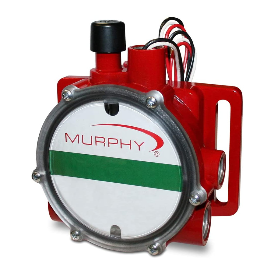
The Murphy LM500 model maintains the crankcase oil level of an engine, pump or compressor. Adjusted to the correct running-oil-level, the LM500 will replenish oil as it is used. The low-level switch will alarm and/or shutdown the equipment if the supply oil is lost and the equipment continues to use oil. -
Page 6: Operating The Range Of The Snap Switch
Operating the Range of the Snap Switch Figure 1 shows the LM500 dial and the operating range of the switch. If level is within the designated zones, the switch will activate. The switch activates approximately 1/4 in. (6 mm) from the bottom of the low zone. The dial-in Figure 1 shows that if the level continues to drop into the low-low zone, a shutdown will occur. -
Page 7: Thumb-Valve Tm Operation
LM500 Series Flow Rates LM500 Series Flow Rates are based on SAE 40 motor oil @2 ft. head pressure. Friction losses due to piping are not considered. -
Page 8: Hose Kit: (P/N 15000355)
Hose Kit: (P/N 15000355) Quantity Description 1/2in (13mm) I.D. x 3ft. (914mm) long hose. 1in (25mm) I.D.x 3ft (914mm) long hose. 1/2in (13mm) worm gear clamp 1in. (25mm) worm gear clamp 1/2NPT x 1/2in. (13mm) barbed fitting Vent Fittings Kit: (P/N 15000954) Quantity Description Tubing vent... -
Page 9: Typical Installation
Pipe Bracket Mounting (PM) (P/N 15000518) 1. Mount a nominal 1/2in. (13mm) diameter pipe to the base of the engine. 2. Install the pipe bracket to the lM500 using two 1/4-20 UNC x 1 inch bolts; nuts and lock washers supplied. See Figure 2A. -
Page 10: Crankcase (Oil Pan) Mounting
2. Mount the LM500 to the universal bracket using two 1/4-20 UNC x 1-1/4 inch (32mm) bolts; flat and lock washers supplied (Figure 3B). DO NOT tighten the adjustment screws too tight as you will have to adjust the LM500 later in the installation process. -
Page 11: Connecting Fittings And Hoses
2. Mount the LM500 to the universal bracket using two 1/4-20 UNC x 1-1/4 inch bolts, flat and lock washers supplied. DO NOT tighten the adjustment bolts to tight as height adjustment might be needed later during the operation. Refer to “Connecting Fittings and Hoses”... -
Page 12: Connecting The Lm500 To An Oil Supply Tank
Install the oil inlet connection. 2. Connect a 1/2inch I.D. (13mm) or larger hose to the oil inlet fitting on the LM500 and to the shutoff valve on the oil supply tank. See Figure 6. Recommended minimum height above the LM500 is 2 ft. -
Page 13: Specifications
Specifications Crankcase Balance Vent Connection: 1/2 NPTF (top). Inlet Connection: 2 x 3/4 NPTF (side) 1 x 3/4 NPTF (bottom) Thumb-Valve Material: Viton Snap-switch: SPDT rating 10 A, 125 VAC; 0.5 A, 125 VDC; 10 A, 30 VDC Wire leads: 18 AWGT x 14 in +/- 2 in (355 mm) length. Conduit Connection: 1/2 inch conduit (female, top).
Need help?
Do you have a question about the LM500 and is the answer not in the manual?
Questions and answers