Murphy M5081FS Installation And Operation Instructions Manual
M2582 series, m5081 series, m5180 series electromechanical and pneumatic, fuel gas shutoff valves
Hide thumbs
Also See for M5081FS:
- Owner's manual (4 pages) ,
- Installation and operation instructions manual (12 pages)
Table of Contents
Advertisement
Quick Links
M2582, M5081, and M5180 Series
Electromechanical and Pneumatic, Fuel Gas Shut-
off Valves Installation and Operation Instructions
Please read the following instructions before installing. A visual inspection of this product for damage during shipping is
recommended before mounting. It is your responsibility to have a qualified person install the unit and make sure installation
conforms with NEC and local codes.
WARNING
BEFORE BEGINNING INSTALLATION OF THIS MURPHY PRODUCT
✔
Disconnect all electrical power to the machine.
✔
Make sure the machine cannot operate during installation.
✔
Follow all safety warnings of the machine manufacturer.
✔
Read and follow all installation instructions.
M2582 and M5081Series
Tripping Power From Engine Ignition System or Battery
(Models available for magneto, CD ignition or 12/24 V battery)
These fuel shut-off valves are semi-automatic devices for shutdown of
natural gas fueled engines. The standard valve opens by manual
operation of the reset handle. A latch in the upper body of the valve will
set and hold the valve open. At this point no electric power is used.
The electromagnetic coil is de-energized, the snap-switch(es) is SET.
If a SWICHGAGE
contact closes, a circuit is completed from power
®
through the snap-switch and coil. Now energized, the electromagnet
trips the latch, (latch can be tripped manually), the valve closes, and the
snap-switch resets. Power switches from the coil circuit to your choice
of an open line, an electrical ground, or an alarm. After tripping, the
vent seal opens, and on the M50 models, the open/close indicator (green
button) retracts to indicate that the valve is closed.
Valve body is sandcast aluminum. Optional cast steel for M5081 models.
M2582-P and M5180-P
MURPHY-NUMATIC
™
Pneumatic Version for Pressure
The M2582-P and M5180 pneumatically controlled valves can operate
from pressure, and are designed to open and close automatically or semi-
automatically (the supply can be air, oil or gas).
NOTE: If using oil as a pressure source, use a lightweight oil.
These valves will open on rising control pressure and close on
decreasing control pressure. M2582-P and M5180-P automatically open
at 2 psi (14 kPa) [0.14 bar] and fully open at 3 psi (21 kPa) [0.21 bar].
All models include a built-in lever to aid in opening the valve manually.
The M2582-P can be manually opened against inlet pressure of 80 psi
(552 kPa) [5.52 bar]. The M5180-P valve can be opened against inlet
pressure of 100 psi (689 kPa) [6.89 bar].
Standard models include an escape vent for gas trapped forward in the
line after shut-off.
1-800-548-1191 - http://www.partdeal.com - info@partdeal.com
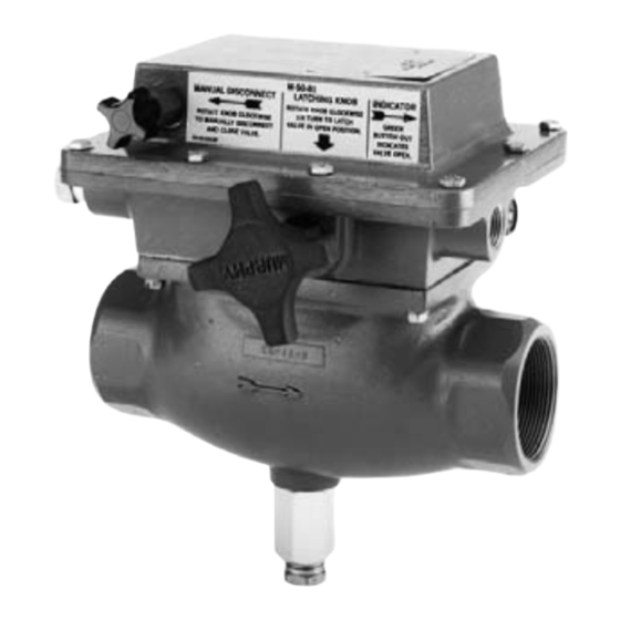
GENERAL INFORMATION
M5081FS
Normally Energized Circuit
The M5081FS is manually opened, electrically latched open and tripped
by interrupting the coil power circuit.
Magnetic Switch Adapter
As ignition systems wear from usage, their power output becomes less
and less. Ignition may not have the capacity to reliably trip the Fuel
Valve. Therefore, the use of a Magnetic Switch Adapter for CD
ignition systems is recommended. The Magnetic Switch Adapter is a
device that stores energy from the CD ignition to trip the Fuel Valve.
Three models are available:
65700053 (was 65020126): For use with negative ground ignitions
up to 240 VDC.
65700054 (was 65020127): For use with positive ground ignitions
up to 450 VDC.
65700055 (was 65020155): For use with negative ground ignitions
up to 450 VDC.
100 ohm, 2 watt Resistor
For Capacitor Discharge Ignitions that are specified to be grounded when
the valve closes, and a Magnetic Switch Adapter is in use. The resistor
must be connected in the system to prevent damage to the snap-switches
in the fuel shut-off valve (see typical wiring diagrams).
Diode Package
The Murphy diode package (65010065) is designed to allow the fuel shut-
off valve to be used with dual Magneto Ignition systems.
NOTE: All aluminum versions of the M5081 Series Fuel Valve carry
Canadian Registartion Number OC1476.2.
* M5081 model is CSA approved for Class I, Division 1, Groups C and D.
See Specifications on page 12.
Installation M-7980N page 1 of 12
Model M5081
M-7980N
Revised 11-02
Section 55
(00-02-0206)
*
Approved
Advertisement
Table of Contents

Related Manuals for Murphy M5081FS


Summary of Contents for Murphy M5081FS
- Page 1 Diode Package decreasing control pressure. M2582-P and M5180-P automatically open The Murphy diode package (65010065) is designed to allow the fuel shut- at 2 psi (14 kPa) [0.14 bar] and fully open at 3 psi (21 kPa) [0.21 bar]. off valve to be used with dual Magneto Ignition systems.
-
Page 2: Flow Characteristics
B. Pressure Disc/seal (in run/open) C. Pressure Disc/seal (in trip/closed) [50.8] D. Vent Seal Gland E. Reset Knob (latches valve open) F. Manual Trip Knob (not available for M5081FS) [25.4] G. Indicator Button (out with valve open) H. Pipe Plug 1000... - Page 3 DIMENSIONS CAUTION: THE ARROW ON THE SIDE OF THE FUEL VALVE MUST POINT TO THE CORRECT DIRECTION OF THE FLOW, FROM FUEL SOURCE TO THE ENGINE. APPLY PIPE DOPE ONLY TO FUEL PIPE, NOT TO THE FUEL VALVE. M2582 M2582-P 1/4 in.
- Page 4 CAUTION: THE ARROW ON THE SIDE OF THE FUEL VALVE MUST POINT TO THE CORRECT DIRECTION OF THE FLOW, FROM FUEL SOURCE TO THE ENGINE. APPLY PIPE DOPE ONLY TO FUEL PIPE, NOT TO THE FUEL VALVE. M5081 and M5081FS 1/2 NPT Conduit Manual Trip Knob Connection (2 plcs.)
-
Page 5: Installation
INSTALLATION WARNING: STOP THE ENGINE AND DISCONNECT ALL ELECTRICAL POWER BEFORE BEGINNING INSTALLATION. BEGIN THE INSTALLATION BY SECURING AREA OF ANY HAZARDOUS CONDITIONS. SHUTOFF THE FUEL GAS SUPPLY. FOR HAZARDOUS APPLICATIONS REFER TO NATIONAL ELECTRICAL CODE SPECIFICATIONS. Connecting the Fuel Shut-off Valve Figure 1 1. -
Page 6: Wiring Information
For typical Wiring refer to page 8. Connect the Magnetic Switch Adapter between the fuel Valve For wiring the M5081FS to MARK IV 12/24 refer to page 10. and 11). terminal 1 and the CD Ignition. See wiring diagrams (pages 7... - Page 7 TYPICAL WIRING for M5081-C (CD IGNITION MODELS) M5081-C Magnetic CD Ignition Models Switch Adapter GND ALT1 ALT2 SW Terminal Block Additional CD ignition CD ignition Ground Jumpers 100 ohm, 2 watt Resistor (Notes 3 and 4) Start-run timer MS2100 MS2100 To additional ®...
- Page 8 NOTE 4: To CLOSE FUEL VALVE and GROUND THE IGNITION (Dual Magneto Systems) Remove the jumper on terminals 9-8. Add 65010065 diode package as shown. Add ground wire to terminal 5. TYPICAL WIRING for M5081FS (NORMALLY ENERGIZED MODELS) M5081FS 12 or 24 VDC Models...
- Page 9 TYPICAL WIRING to SOLID-STATE TATTLETALE ® Annunciators WARNING: PERFORM THE WIRING OPERATION WITH THE POWER SOURCE “OFF” AND THE AREA MADE NON- HAZARDOUS. MAKE SURE THE VOLTAGE AND CURRENT REQUIREMENTS ARE WITHIN THE FUEL SHUT-OFF VALVE RATINGS. HARD CONDUIT WITH APPROVED SEALS IS REQUIRED BY THE NEC FOR HAZARDOUS AREA INSTALLATIONS. M2582-C to LCDT-PS-CD (R)-P (positive ground) M5081-C to LCDT-PS-CD (R)-P (positive ground) LCDT-PS-CD (R)-P...
- Page 10 PERFORM THE WIRING OPERATION WITH THE POWER SOURCE “OFF” AND THE AREA MADE NON- HAZARDOUS. MAKE SURE THE VOLTAGE AND CURRENT REQUIREMENTS ARE WITHIN THE FUEL SHUT-OFF VALVE RATINGS. HARD CONDUIT WITH APPROVED SEALS IS REQUIRED BY THE NEC FOR HAZARDOUS AREA INSTALLATIONS. M5081FS to MARK IV-12/24 M5081-B to MARK IV-12/24 M5081-B...
- Page 11 Class I, Div. 2, Gps. C & D areas. * 1N4005 diode for flyback protection TTDJ-DC-(T) to Relays M5081FS to TTDJ-DC-(T) Connections Shown for Use with Diagrams (A), (B), (C), and (D) on this page. To 12 or 24 VDC...
-
Page 12: Specifications
------------ 65700055 Warranty A limited warranty on materials and workmanship is given with this FW Murphy product. A copy of the warranty may be viewed or printed by going to www.fwmurphy.com/support/warranty.htm CONTROL SYSTEMS & SERVICES DIVISION FRANK W. MURPHY, LTD.
Need help?
Do you have a question about the M5081FS and is the answer not in the manual?
Questions and answers