
Related Manuals for Murphy Xpansion IX3212


Summary of Contents for Murphy Xpansion IX3212
- Page 1 Intelligent pansion Series IX3212 PDM Reference Manual 00-02-0829 2018-02-26 Section 80...
- Page 2 Please read the following information before installing. BEFORE BEGINNING USE OF THIS PRODUCT: Read and follow all instructions. Please contact Enovation Controls immediately if you have any questions.
-
Page 3: Table Of Contents
CONTENTS INTRODUCTION ................................3 ..................................3 VERVIEW ..................................5 ESCRIPTION ........................6 OTATION ONVENTIONS SED IN THE ANUAL INSTALLATION ................................7 ..............................7 OUNTING RIENTATION ..................................8 IMENSIONS ................................9 IRCUIT ROTECTION ............................9 ECOMMENDED IRING RACTICES ELECTRICAL CONNECTIONS ............................11 J2 .............................. - Page 4 4.4.1.4 Module Transmit Rate ............................... 37 .............................. 38 EEDBACK AND IAGNOSTICS 4.5.1 Analog Inputs 1-2, Digital Feedback ........................39 4.5.1.1 Feedback and Diagnostics Identifier .......................... 40 4.5.1.2 Digital Inputs ................................40 4.5.1.3 Analog Inputs ................................41 4.5.2 Analog Inputs 3-4, Output Diagnostics ......................42 4.5.2.1 Output Diagnostic ..............................
-
Page 5: Introduction
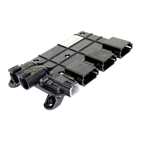
1 Introduction 1.1 Overview Murphy’s Intelligent Xpansion™ Power Distribution Module (PDM) expands CAN bus networks and replaces existing fuse and relay boxes with more reliable, solid-state switches that can directly drive lights, cooling fans, wiper motors and directional DC motors. - Page 6 The PDM features a compact, composite polymer aluminum housing and can operate in either 12V or 24V systems. The solid construction and compact enclosure facilitate mounting anywhere on the vehicle. The PDM provides a novel alternative to current relay/fuse-based solutions. The PDM is potted and has no mechanical parts.
-
Page 7: Description
1.2 Description The IX3212 PDM is a robust, compact, fully encapsulated unit and is designed for off-highway mobile equipment and other industrial applications. It features 12 tri-state digital inputs, eight analog inputs and 12 high-current (15 A) high-side outputs. The unit also features a fully protected 5V sensor supply capable of driving 70 mA. The 12 high-current outputs can be configured as H-Bridge pairs. -
Page 8: Notation Conventions Used In The Manual
1.3 Notation Conventions Used in the Manual This document features Adobe Reader bookmarks to quickly jump between sections. Additionally, blue-colored hyperlinks are used throughout the manual to allow easy navigation between the various CAN messages. Section 80 00-02-0829 2018-02-26 - 6 -... -
Page 9: Installation
2 Installation 2.1 Mounting Orientation The PDM should be mounted on a vertical surface with either J3 – J6 facing down or to the right. Secure the module with either 6 mm or 1/4 in. diameter fasteners. IMPORTANT: The harness should have a drip loop(s) to allow water to run off the wires. -
Page 10: Dimensions
2.2 Dimensions IX3212 PDM Dimensions Section 80 00-02-0829 2018-02-26 - 8 -... -
Page 11: Circuit Protection
2.3 Circuit Protection A fuse or circuit break on the positive power input (connector J2) is required and should be located near the power source (e.g. battery). The outputs are monitored for over-current conditions and turn-off in the event of the fault. For information on how to configure the output current limit, refer to Section 4.3.2 –... - Page 12 o Insure that the voltage drop at the load is kept within the recommended 10 percent maximum level for the respective 12V or 24V power system. • Wire gauge reductions are permissible after the point at which circuit protection is added or enabled.
-
Page 13: Electrical Connections
3 Electrical Connections 3.1 Connectors J1 and J2 The connector pinout is as viewed looking into the PDM receptacles or from the wire side of the mating plugs. − Mating Connector FUNCTION LIMIT Ground 70 A continuous (return) DTHD 06-1-4S 70 A continuous (source) DTHD 06-1-4S BATT... -
Page 14: Connector J3
3.2 Connector J3 The connector pinout is as viewed looking into the PDM receptacles or from the wire side of the mating plugs. Function Limit Mating Connector J3-1 5V Regulated Output 5 V @ 70 mA (both pins) GND (Isolated) J3-2 Digital Input 12 0-28 VDC... -
Page 15: Connector J4
3.3 Connector J4 The connector pinout is as viewed looking into the PDM receptacles or from the wire side of the mating plugs. Function Limit Mating Connector J4-1 Digital Output 1 15 A (PWM @ 500 Hz) J4-2 Digital Output 2 15 A (PWM @ 500 Hz) J4-3 Digital Output 3... -
Page 16: Connector J5
3.4 Connector J5 The connector pinout is as viewed looking into the PDM receptacles or from the wire side of the mating plugs. FUNCTION LIMIT Mating Connector J5-1 CAN LOW J5-2 Digital Input 3 0 – 28 VDC J5-3 Digital Input 4 0 –... -
Page 17: Connector J6
3.5 Connector J6 The connector pinout is as viewed looking into the PDM receptacles or from the wire side of the mating plugs. FUNCTION LIMIT Mating Connector J6-1 Digital Output 12 15 A (PWM @ 100 Hz) DTP06-2S J6-2 Digital Output 11 15 A (PWM @ 100 Hz) NOTE: Deutsch DT series contacts are size 16. -
Page 18: Communication
4 Communication 4.1 Overview The IX3212 PDM uses proprietary SAE J1939 CAN messages to configure control, and communicate the I/O status. PowerView displays or a compatible CAN 2.0B CAN bus device can be used to send CAN messages. Each CAN message has an identifier in the first byte that determines the message context. There are five unique identifiers associated with command and configuration and nine unique identifiers associated with input status, feedback, diagnostics and data reported by the PDM. -
Page 19: Output Modes
4.1.3 Output Modes Two slave modes of operation are possible where the PDM is configured and controlled by a PowerView display or some other CAN bus controller. 1. High-Side Switch (HSS): This mode of operation is the typical standard output to turn a load on or off. -
Page 20: Naming And Numbering Conventions
4.2 Naming and Numbering Conventions The byte/bit order is represented in the following figure. Bit 1 is the least significant bit (lsb) and Bit 8 is the most significant bit (msb). Byte 1 is the transmitted first and Byte 8 is last (i.e. sequential). - Page 21 Bit placement is sequential from the starting byte/bit position. For example, an analog input is expressed as a 10 bit value in 2 bytes of data. The start position is given as 2.2 meaning byte 2, bit 2. The 10 bits are ordered starting in byte 2, bit 2 and continue throughout byte 1. The illustration below shows the numeric value 221 (DDh) or 00 1101 1101 in binary format in the dark gray portion.
-
Page 22: Configuring
4.3 Configuring The IX3212 PDM is configured via the CAN bus messages for either slave or LSC (autonomous) operation. In the slave configuration, where a PowerView display or a CAN bus controller is controlling the PDM, it is recommended that the configuration messages be sent on every power-up. -
Page 23: Configure Output Function
4.3.1 Configure Output Function The Configure Output Function message sets the mode, power-on characteristics and general behavior for each output. The message must be sent at least one time for LSC and as often as required if the output configuration needs to change. A handshake message is returned by the PDM to confirm the setup. -
Page 24: Configuration Identifier
4.3.1.1 Configuration Identifier This identifier is a secondary address that indicates the type of message, in this case output functionality. 0 Output Configuration Data Length: 1 byte Resolution: 5 states / 1 byte 0 offset Data Range: Operational Range: same as data range Type: Status (command) PGN:... - Page 25 For example, a soft-start value of 10% using lamp mode means that the PDM reaches 100% after 680 ms. Whereas the same 10% value using motor mode takes 5,000 ms to reach 100%. The illustrations below show the time base of an example 10% PWM value. Command (Motor Mode) Command (Lamp Mode) Elapsed Time (ms)
-
Page 26: Motor/Lamp Mode
4.3.1.4 Motor/Lamp Mode The over-current profile can be selected depending on the type of load. See the current profile in the figures below. 0 Lamp 1 Motor Data Length: 1 byte Resolution: 2 states / 1 byte 0 offset Data Range: 0 to 1 Operational Range: same as data range... -
Page 27: Loss Of Communication
DC motors or inductive loads such as relays exhibit a delayed inrush or stall current. A window-shaped profile for the overcurrent and overheating protection is pre-programmed at the factory. The motor mode peak current is limited to 43.3 A nominally for up to 429 ms. The final level is set at up to 15 A continuous current. -
Page 28: Por Command
4.3.1.6 POR Command The POR Command sets the percentage PWM level for each output at module power on/reset. This establishes the output PWM level an individual output will be commanded to at start up. This can be useful in many applications, but because the PDM is no longer under supervisory control, appropriate testing should be conducted to ensure safe operation. -
Page 29: Por Enable
POR Command Value Commanded PWM % Actual PWM % 11010 -37.5 -37.5 11001 -43.75 -43.75 11000 10111 -56.25 -56.25 10110 -62.5 -62.5 10101 -68.75 -68.75 10100 10011 -81.25 -81.25 10010 -87.5 -87.5 10001 -93.75 -93.75 10000 -100 -100 4.3.1.7 POR Enable POR enables the above power on reset functionality for the individual output. -
Page 30: Motor Braking
4.3.1.9 Motor Braking Motor braking for H-bridge controlled outputs. This enables motor braking for the specific H-Bridge pair. 0 Disabled 1 Enabled Data Length: 1 bit Resolution: 2 states / 1 bit 0 offset Data Range: 0 to 1 Operational Range: same as data range Type: Status (command) -
Page 31: Response
4.3.1.12 Response Response indicates how the output channel turns-on depending on the input is active low, high or both (either low or high). 00 Reserved 01 Active Low 10 Active High 11 Active Low or High Data Length: 2 bits Resolution: 2 states / 2 bits 0 offset... -
Page 32: Configure Output Channels
4.3.2 Configure Output Channels The following CAN message also configures the outputs in two groups. Configure Output Channels is a message sent to the PDM to set up the high-current output channels as a single high-side output or as an H-bridge pair. It also sets the current limit and reset behavior. Depending on the output configuration identifier, the message applies to either output channels 1-6 or 7-12 respectively. -
Page 33: Output Channel Group Identifier
4 bits Current Limit (Output Channel 5 or 11) 4.3.2.2 2 bits Feedback Type (Output Channel 5 or 11) 4.3.2.3 1 bit Automatic Reset (Output Channel 5 or 11) 4.3.2.3 1 bit High-Side or H-Bridge (Output Channel 5 or 11) 4.3.2.5 4 bits Current Limit (Output Channel 6 or 12) -
Page 34: Feedback Type
4.3.2.3 Feedback Type Feedback type is always set to Current. The other modes are not supported on the IX3212-24. 00 Position feedback (not supported on the IX3212-24) 01 Rate feedback (not supported on the IX3212-24) 10 Power feedback (not supported on the IX3212-24) 11 Current feedback (always) Data Length: 2 bits... -
Page 35: High-Side Or H-Bridge
4.3.2.5 High-Side or H-Bridge High-side or H-Bridge configures either a single output for driving discrete loads or assigns a pair of outputs for directional motor control. H-Bridge pairs are grouped as follows: 1 and 2, 3 and 4, 5 and 6, etc. Note: When configuring the output for H-bridge operation, the second channel in the pair (even number) must have byte 2 set to 255. -
Page 36: Commanding
4.4 Commanding After the configuration is complete, the IX3212 outputs can be commanded. The following message type defines how to command the PDM: • Command Output Channels Section 80 00-02-0829 2018-02-26 - 34 -... -
Page 37: Command Output Channels
4.4.1 Command Output Channels The command output channels message sets the PWM value of each output channel. The message bytes refer to outputs 1-6 or 7-12, depending on the value of the identifier in the first byte. NOTE: A Command message must be broadcast to the PDM at least once every second. -
Page 38: Output Command Identifier
4.4.1.1 Output Command Identifier This value defines which output channels the Command Output Channels message is referencing. 4 Output Channels 1-6 5 Output Channels 7-12 Data Length: 1 byte Resolution: 2 states / 1 byte 0 offset Data Range: 4 or 5 Operational Range: same as data range Type:... -
Page 39: Enable
4.4.1.3 Enable This value defines whether the specified channel is enabled or disabled. NOTE: When a channel is disabled, it must have byte 2 set to 255 (FFh). 0 Disabled 1 Enabled Data Length: 1 bit Resolution: 2 states / 1 bit 0 offset Data Range: 0 or 1... -
Page 40: Feedback And Diagnostics
4.5 Feedback and Diagnostics The IX3212 PDM will periodically transmit feedback messages with the measured analog values and handshake. The following message type defines how to command the PDM: • Analog Inputs 1-2, Digital Inputs Feedback • Analog Inputs 3-4, Output Diagnostics •... -
Page 41: Analog Inputs 1-2, Digital Feedback
4.5.1 Analog Inputs 1-2, Digital Inputs Feedback The analog channel feedback is the value of the input signal on the respective channel with 10 bit resolution. The digital input indicates if the input is open (floating), connected to ground or the battery. -
Page 42: Feedback And Diagnostics Identifier
4.5.1.1 Feedback and Diagnostics Identifier All feedback and diagnostic messages contain a unique identifier which determines the associated information. 128 (80h) Analog Inputs 1-2, Digital Inputs 129 (81h) Analog Inputs 3-4, Output Diagnostics 130 (82h) Analog Inputs 5-6, Battery and Sensor Supply 131 (83h) Analog Inputs 7-8, Miscellaneous Feedback 132 (84h) Outputs 1-6 Feedback 133 (85h) Outputs 7-12 Feedback... -
Page 43: Analog Inputs
4.5.1.3 Analog Inputs Each analog input is represented by a 10-bit raw value for the 0-5V range by using two bytes. LSB (8 bits) MSB (2 bits) Data Length: 2 bytes Resolution: 10 bits 0 offset Data Range: 0-1023 Operational Range: same as data range Type: Status (command) -
Page 44: Analog Inputs 3-4, Output Diagnostics
4.5.2 Analog Inputs 3-4, Output Diagnostics The analog channel feedback is the value of the associated analog inputs. The analog input is represented by a 10 bit raw value for the 0-5 V range. The output diagnostics indicate: no fault, a short-circuit, an over-current condition or an open-circuit. CAN message sent by the PDM to communicate the measured values of Analog Inputs 3 and 4 as well as the Output diagnostics. -
Page 45: Output Diagnostic
4.5.2.1 Output Diagnostic Output channel diagnostic status. 00 No faults 01 Short-circuit 10 Over-current 11 Open-circuit Data Length: 2 bits Resolution: 4 states / 2 bits 0 offset Data Range: Operational Range: same as data range Type: Status (measured) PGN: PGN 61184 –... -
Page 46: Analog Inputs 5-6, Battery And Sensor Supply
4.5.3 Analog Inputs 5-6, Battery and Sensor Supply The analog channel feedback is as follows: The analog input is represented by a 10 bit raw value for the 0-5 V range. The Sensor supply bits indicate the supply is OK when the bit is high (1). -
Page 47: Sensor Supply Low
4.5.3.1 Sensor Supply Low 5V sensor supply is out of range low. 0 5V output too low 1 5V output OK Data Length: 1 bit Resolution: 0 offset Data Range: Operational Range: same as data range Type: Status PGN: PGN 61184 – Feedback and Diagnostics 4.5.3.2 Sensor Supply High 5V sensor supply is out of range high. -
Page 48: Analog Inputs 7-8, Software Version And Power Supply
4.5.4 Analog Inputs 7-8, Software Version and Power Supply CAN message sent by the PDM to communicate the measured values. Transmission Repetition 20 – 500 ms Data Length 8 bytes Data Page PDU Format (PF) Proprietary A, PDU1 format DA (Source Address of the configuring display or PDU Specific (PS) 17 (11h) controller) -
Page 49: Total Current Status
4.5.4.1 Total Current Status Total current status. 0 Total current too high 1 Total current OK Data Length: 1 bit Resolution: 0 offset Data Range: Operational Range: same as data range Type: Status PGN: PGN 61184 – Feedback and Diagnostics 4.5.4.2 Power Supply Status Power supply status. -
Page 50: Output Feedback
4.5.5 Output Feedback WARNING: Closed-loop proportional control is not recommended due to the non- deterministic nature of the CAN bus. CAN message sent by the PDM to communicate the measured values of the digital outputs channels. Transmission Repetition 20 – 500 ms Data Length 8 bytes Data Page... -
Page 51: Current, Power, Position Or Rate Feedback
4.5.5.1 Current, Power, Position or Rate Feedback Note: Only current feedback is supported. Current Feedback, resolution of 0.125 A / lsb Power Feedback, 1 W / LSB Position Feedback, 1% / LSB, offset 75%, range -75 to 180% Rate Feedback, .25 % / sec / LSB, range 0 to 63.75% Data Length: 1 byte Resolution:... -
Page 52: Output Function Handshake
4.5.6 Output Function Handshake The handshake message is sent back every time a configuration message is received as an acknowledgement of the output channel setup. The handshake message is also sent once per second thereafter for a means of checking the output configuration. CAN message sent by the PDM to communicate the output channel number, soft-start parameters, motor/lamp mode, loss of communication and other output controls. -
Page 53: Output Configuration Handshake
4.5.7 Output Configuration Handshake After the output channels settings are sent to the PDM, the stored settings are then broadcast back to the configuring device in order to verify the intended configuration. Only after the settings are in agreement should the output be enabled. CAUTION: Use this message to verify the output settings prior to enabling any output. - Page 54 This CAN message is broadcast by the PDM to communicate the settings of a group of output channels. Depending on the Feedback and Diagnostics Identifier byte, the message pertains to Output Channels 1-6 or 7- 12 respectively. Transmission Repetition 20 – 500 ms Data Length 8 bytes Data Page...
-
Page 55: Example Messages
4.6 Example Messages 4.6.1 Arbitration Field The IX3212 PDM follows SAE J1939-21, which defines proprietary Parameter Group Numbers (PGNs). The Protocol Data Unit (PDU) is the bit arbitration field of every message on the CAN bus. The first three bits are the Priority (P) of the message. The recommended value is 5h (5). When combined with the Reserved (R) bit and Data Page (DP) bit, the value becomes 14h (20). -
Page 56: Example Pseudo Code
4.7 Example Pseudo Code These are example program flows to configure, command and read the feedback messages. 4.7.1 Configure and Verify Outputs The following pseudo code outlines the possible steps to take in configuring the PDM: FOR Outputs 1-12 CONFIGURE Output n function READ Output n function handshake VERIFY Output n function ENDFOR... -
Page 57: Troubleshooting
5 Troubleshooting 5.1 Output Does Not Respond Check the battery or power supply connection. Check the power supply rating. • The PDM switches a high amount of current. Many power supplies are incapable of sourcing adequate current. Using a battery is the preferred method for powering the PDM. -
Page 58: Specifications
6 Specifications Operating Voltage: 12V/24V nominal (8-32 V) Reverse polarity protection Operating Current: Total: 70 A, simultaneous active outputs Standby (idle) current draw: <100 mA, 80 mA typical Sleep current draw: 35 mA typical Inputs: Digital: 12 digital tri-state (high-side, low-side, open) Input impedance: 7.7 kΩ... - Page 59 Deutsch DTP series 2 pin (J6); Deutsch DT HD power series 1 pin (J1 and J2). Environmental: Operating Temperature: -40°C to +85°C (-40°F to +185°F) Storage Temperature: -40°C to +135°C (-40°F to +275°F) Environmental Sealing: IP 66 and 67 Shock: 30 G, 3 cycles Vibration: 5 –...
-
Page 60: Condensed Message Definition
7 Condensed Message Definition PDM Receive Messages Byte 1 Byte 2 Byte 3 Byte 4 Byte 5 Byte 6 Byte 7 Byte 8 Configure Output Function Output Channel Soft-Start Step Size Motor/Lamp Mode Loss of Comm POR, Cmd, Braking LSC, Response Configure Outputs 1-6 Output 1 Config Output 2 Config... - Page 61 NOTES...
Need help?
Do you have a question about the Xpansion IX3212 and is the answer not in the manual?
Questions and answers