
Related Manuals for ElektroPhysik MiniTest 2500


Summary of Contents for ElektroPhysik MiniTest 2500
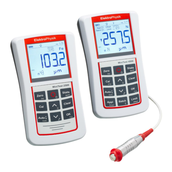
- Page 1 ElektroPhysik Operating instructions Coating thickness gauges MiniTest 2500 and MiniTest 4500...
- Page 2 Version 1.0 14.06.2018 Germany Gauge software Version: from 1.0.1 Tel.: +49 221 752040 Sensor Software: from 1.0 Fax.: +49 221 7520467 Subject to technical change without notice. Internet: http://www.elektrophysik.com/ Mail:: info@elektrophysik.com © ElektroPhysik MiniTest 2500 - MiniTest 4500 2 of 73...
-
Page 3: Table Of Contents
5.4.1 Taking readings without using the sensor stand ............21 5.4.2 High-precision stand ....................22 5.4.3 Duplex coating systems ....................22 5.5 Errors during measurement ....................22 5.6 Measurement on high temperatures using high-temp sensors ..........22 © ElektroPhysik MiniTest 2500 - MiniTest 4500 3 of 73... - Page 4 Method B (roughness Rz < 20µm) ................. 40 7.15.3 Method C Calibration with two calibration foils of different thickness ...... 40 8. Data Management ........................41 8.1 Batches ..........................41 © ElektroPhysik MiniTest 2500 - MiniTest 4500 4 of 73...
- Page 5 Time and date stamp ..................... 51 11.2.6 Time and date ......................51 Measuring unit: ‘metrical’ - Inch’ (imperial) ............. 52 11.2.7 11.2.8 Automatic data transfer in continuous mode ............52 © ElektroPhysik MiniTest 2500 - MiniTest 4500 5 of 73...
- Page 6 „POWER OFF“ Switch off time ................55 11.2.22 11.2.23 SYSINFO ......................55 11.2.24 Table of basic settings for MiniTest 4500 ..............56 11.2.25 Table of basic settings for MiniTest 2500 ..............57 12. Accessories ........................... 58 12.1 General ..........................58 13.
- Page 7 Index © ElektroPhysik MiniTest 2500 - MiniTest 4500 7 of 73...
-
Page 8: Introduction
Modern data administration allows simple access to the internal data memory with maximum storage capacity of up to 2 million measuring values. MiniTest 4500 features a data memory with ‘APPL-BATCH mode’ allowing measurement and storage of readings in a user definable memory. -
Page 9: First Steps
Insert the batteries from the supply schedule observing correct polarity (see illustration). d) Close the battery compartment and fix the lid with the screws. © ElektroPhysik MiniTest 2500 - MiniTest 4500 9 of 73... -
Page 10: Operation Of The Gauge
To take readings, place the sensor in right angle onto the measuring object. The coating thickness will be displayed on the screen after a short while (less than a second). Remove sensor and take next reading. © ElektroPhysik MiniTest 2500 - MiniTest 4500 10 of 73... -
Page 11: Description Of The Measuring System
Note: PC connection via USB active Note: Selected APPL-Batch group Note: Keypad locked Offset note: Offset is activate Limit note: Limits are active Note: Reading is within, above or below preset limits © ElektroPhysik MiniTest 2500 - MiniTest 4500 11 of 73... -
Page 12: Operating Keys
‘ ’ activates and deactivates the Bluetooth Interface (only MiniTest 4500). 3.1.3 Interfaces The model MiniTest 4500 is equipped with a USB and Bluetooth interface. MiniTest 2500 is only equipped with a USB interface. 3.1.4 Power supply 3.1.4.1 Batteries and rechargeable batteries Coating thickness gauges MiniTest 2500 and 4500 are powered by three alkaline-manganese- batteries 1.5V, type AA / LR6 (included in standard supply);... -
Page 13: Sensors
3.2.1 Sensors of the MiniTest 1100 – 2100 - 3100 - 4100 series All sensors of the predecessor series are compatible with coating thickness gauges MiniTest 2500 and MiniTest 4500. However, it is required to perform a one-time adaptation of the sensor to the measurement electronics. -
Page 14: Adaptation Of Sensor Types N10, N20 And N100
MiniTest 1100 / 2100 / 3100 / 4100. The adaptation procedure can be repeated at any time in point 20 of the initial settings. Hold the sensor in a distance to any metal and press ‘OK’. © ElektroPhysik MiniTest 2500 - MiniTest 4500 14 of 73... -
Page 15: Measuring, Storage And Data Processing In Direct Or Appl-Batch Mode
Number of unit readings The model MiniTest 4500 offers two different working modes: ‘DIRECT mode’ and ‘APPL- BATCH mode’. ‘DIRECT mode’ is intended for quick occasional readings. Readings as well as the 6 statistical values (8 if limits have been set) can be shown on the display and printed by pressing STATS’. - Page 16 When pressing the APPL-BATCH key, the pair of numbers of the last active APPL-BATCH memory will be shown on the display. The gauges switches off automatically according to the selected switch-off-time after the last measurement (see also section 11.1 initial settings). © ElektroPhysik MiniTest 2500 - MiniTest 4500 16 of 73...
-
Page 17: Structure Of The Appl-Batch System
4. Measuring, Storage and Data Processing in DIRECT or APPL-BATCH mode Structure of the APPL-BATCH system MiniTest 2500 and MiniTest 4500 generally group reading in series of measurements in one memory batch. MiniTest 2500 features one fixed memory (DIRECT) whereas MiniTest 4500 features one DIRECT memory and 99 application memories (APPL) combined with memories for series of measurements (BATCH). -
Page 18: Switching Appl-Batch Mode On / Off
4. Measuring, Storage and Data Processing in DIRECT or APPL-BATCH mode Illustration: APPL-BATCH memory With MiniTest 4500 99 application memories (APPL-memory lines) – subdivided in 99 BATCH- memory columns each, i.e. 9,801 memories in total, are available. Several million readings can be logged to the memory. -
Page 19: Displaying The Number Of Active Appl-Batch
If required, use the arrow keys to select a new BATCH no. Keep the key pressed down for quickly scrolling through the memory until a free BATCH number is found. The number will then be displayed, e.g. <3 : 8>. Press BATCH to confirm. © ElektroPhysik MiniTest 2500 - MiniTest 4500 19 of 73... -
Page 20: Measuring
Limit setting (see section 8.4) Offset setting (see section 8.2) All readings will be stored to the active APPL-BATCH memory. Note: Limits can still be set after readings have been taken. © ElektroPhysik MiniTest 2500 - MiniTest 4500 20 of 73... -
Page 21: Preparing Measurement
Note that grinding movements on the measuring object will affect the sensor pole (small pin in the center of the sensor end surface touching the measuring object) and lead to abrasion which should be prevented in order to maintain the high precision of the gauge. © ElektroPhysik MiniTest 2500 - MiniTest 4500 21 of 73... -
Page 22: High-Precision Stand
5.6 Measurement on high temperatures using high-temp sensors The measuring system MiniTest 2500 / MiniTest 4500 (gauge + sensor) is designed for a maximum operating temperature of 50°C / 122°F for the gauge and 70°C / 158°F, at short periods 120 °C / 248°F for the sensor. - Page 23 Keep the sensor away from hot measuring objects to prevent heating up through heat radiation. Sensor recovery times in high-temp operation Temperature / °C Temperature / °F Recovery time / s © ElektroPhysik MiniTest 2500 - MiniTest 4500 23 of 73...
-
Page 24: Calibration
(see illustration). The precision thickness standards must be handled with care. Any wear-and tear of the thickness standard will be reflected as erratic calibration value. Do not fold calibration foils. © ElektroPhysik MiniTest 2500 - MiniTest 4500 24 of 73... -
Page 25: Calibration Methods
It is recommended to choose a precision standard to cover the lower half of expected thickness range, the other one should be in the higher half of expected thickness range. © ElektroPhysik MiniTest 2500 - MiniTest 4500 25 of 73... -
Page 26: Two-Point Calibration Without Zero
“ and confirm with the “OK” key. . If no selection is made at all, the gauge will automatically display FERROUS after about 5 secs. And select the magnetic induction method. © ElektroPhysik MiniTest 2500 - MiniTest 4500 26 of 73... -
Page 27: Calibration
ZERO calibration by repeating steps 1 to 3 above. This automatically deletes the old calibration and saves the new one. Note: ZERO calibration deletes any existing CAL calibration. © ElektroPhysik MiniTest 2500 - MiniTest 4500 27 of 73... -
Page 28: Two-Point Calibration (Zero Setting Plus One Calibration Foil)
The calibration standards must be of the same metal as the actual coating. Under certain circumstances, this may also apply to F probes with a low measuring range. © ElektroPhysik MiniTest 2500 - MiniTest 4500 28 of 73... -
Page 29: Multi-Point Calibration (Zero Setting Plus Up To Four Calibration Foils)
The thickness of the foil should be roughly equivalent to the estimated coating thickness. Apply the probe to the test sample several times. The display always shows the mean value of the previous readings. To discontinue calibration, press CLEAR. © ElektroPhysik MiniTest 2500 - MiniTest 4500 29 of 73... -
Page 30: Two-Point Calibration Using Two Calibration Foils Without Zero Calibration
400µm F50: min. 1000µm (1mm) N100: min. 5000µm (5mm) All other sensors: min. 25µm For best results, the thickness to be expected should be somewhere between the two calibration values. © ElektroPhysik MiniTest 2500 - MiniTest 4500 30 of 73... - Page 31 It may be necessary to delete CAL calibration, e.g. after entry of a faulty calibration value: Press CAL and CLEAR key followed by OK key. The second calibration value is now deleted. © ElektroPhysik MiniTest 2500 - MiniTest 4500 31 of 73...
- Page 32 The default standard calibration for flat surfaces is now active. For a new CAL calibration repeat steps 2 -7. The previous calibration is deleted and the new calibration is active. © ElektroPhysik MiniTest 2500 - MiniTest 4500 32 of 73...
-
Page 33: Calibration Through The Coating
If necessary, adjust the value displayed to the thickness value of the calibration foil using the arrow keys. Press OK key shortly to confirm and complete CTC calibration. ‘CTC1’ is displayed steadily. © ElektroPhysik MiniTest 2500 - MiniTest 4500 33 of 73... -
Page 34: Sensors N10 And N20
Press ZERO key several seconds 7.7.2 Two-point calibration (zero setting plus one calibration foil) ZERO flashes Press OK key ZERO steady CAL flashes CAL steady Press OK key Lift sensor Adjust thickness value © ElektroPhysik MiniTest 2500 - MiniTest 4500 34 of 73... -
Page 35: Elimination Of Dielectric Interferences Of The Coating Material
To switch to “Single measurement mode“ press „Auto FN/ Cont“ for several seconds. 7.8.1 Standardization (Acquisition of Infinite Value) ZERO key lange drücken Hold the sensor in the air and press ZERO/ key for several seconds. © ElektroPhysik MiniTest 2500 - MiniTest 4500 35 of 73... -
Page 36: Two-Point Calibration (Zero Setting Plus One Calibration Foil)
10°C. If the gauge is to be used on other types of material, point 7.8.3 must be repeated. © ElektroPhysik MiniTest 2500 - MiniTest 4500 36 of 73... -
Page 37: Sensor F20
In order to avoid hysteresis errors, after each measurement, the probe must be held away from the measuring object ensuring a minimum distance of 0.3m / 12“ away from any metal parts. © ElektroPhysik MiniTest 2500 - MiniTest 4500 37 of 73... -
Page 38: Tube Sensors F1.6/90, F2/90, N1.6/90 And N2/90
Measurements on double-sided laminated PC boards will require calibration using a double sided laminated copper standard. 7.14 Recalibration in an APPL memory line Also refer to diagram 3.1 Structure of the APPL-BATCH system. © ElektroPhysik MiniTest 2500 - MiniTest 4500 38 of 73... - Page 39 APPL memory line in succession, even if these have different calibrations. Note: Only the last recalibration will become valid. Any previous calibration within the same APPL- memory line will become invalid. © ElektroPhysik MiniTest 2500 - MiniTest 4500 39 of 73...
-
Page 40: Shot-Blasted And Rough Surfaces
5...10 readings. The statistics programme is very useful in this context. Note: For coatings thicker than 300 μm, the influence of roughness generally is of no importance and it will not be necessary to apply above calibration methods. © ElektroPhysik MiniTest 2500 - MiniTest 4500 40 of 73... -
Page 41: Data Management
The application memory registers the calibration once performed as well as the sensor connected to the gauge. Once MiniTest 4500 is adjusted to the different measuring tasks, carrying out a sequence of measurements is extremely easy and quick. -
Page 42: Single Values / Continuous Measurement Mode
Return to single measurement mode by repeating point 2. 8.6 Measuring with statistics For MiniTest 4500, two different statistical programs are available: single value statistics and block value statistics (DIN 50982). Within the APPL-BATCH memory system (siehe Section 3) calculates statistics from a maximum of 100 series of readings while MiniTest 4100 is able to calculate statistics from as much as 500 measuring series. -
Page 43: Taking A Series Of Measurement With Statistical Calculation
Deleting outliers or erratic readings Deletion must take place immediately after an outlier orerratic reading has been taken (see also section 9). Press Clear key once. © ElektroPhysik MiniTest 2500 - MiniTest 4500 43 of 73... -
Page 44: Storage Capacity Overflow
E22 "FILE ERROR" appears. Delete unneeded Appl-Batch memories. 8.10 Display or print-out of a series of measurements The MiniTest 4500 features a USB- and a Bluetooth interface, Minitest 2500 only a USB interface. All measuring and statistical values logged to the memory can be: ... -
Page 45: Block Value Statistics
Complete print-out of measuring and statistical values Press and hold Stats/Send key. If the gauge is connected to a printer MiniPrint 7000 BT via Bluetooth (only MiniTest 4500), all measuring values including statistics, date, time and sensor type in use will be printed now. -
Page 46: Deletion
All measuring values and settings of this series of measurements are irrevocably deleted and there is no possibility to restore deleted data. 9.5 Deleting limit values within an APPL-BATCH memory Exampe APPL-BATCH memory <2:3>. © ElektroPhysik MiniTest 2500 - MiniTest 4500 46 of 73... -
Page 47: Deleting All Series Of Measurements Incl. Statistics, Limits And Calibration Values Of An Appl Memory
ON one after the other and hold. “NO“ and „TOTAL RESET“ flashes red Press Clear, key to opt “Yes“ and confirm with OK. An acoustic signal confirms on the display. Use the deletion. © ElektroPhysik MiniTest 2500 - MiniTest 4500 47 of 73... -
Page 48: Data Output And Transfer
10. Data output and transfer 10. Data output and transfer The MiniTest 4500 features a USB- and a Bluetooth interface, Minitest 2500 only a USB interface. All measuring and statistical values logged to the memory can be - printed on a data printer MiniPrint 7000 BT via the Bluetooth interface, - transferred to a PC terminal program MSoft7000 via USB cable or wireless Bluetooth, - send to the APP Miniview for Android Smartphones or Tablets. -
Page 49: Read Out Data Via A Pc
CSV file (BATCH_01.csv) when using MIniTest 4500. The data format CSV implies Comma-separated values and describes the structure of a text file for storage or exchange of data with a simple structure. This data format can be read by common spreadsheet programs as for example Microsoft Excel, Numbers (for Mac OS X ) or Calc ( OpenOffice ). -
Page 50: Further Functions
Successive single values of a measuring series can be condensed to blocks of same size (Blocking or measuring values.). The number of single readings per block is user definable from 1 to 99. A block statistic is created from each block. © ElektroPhysik MiniTest 2500 - MiniTest 4500 50 of 73... -
Page 51: Display Illumination
The setting “TIME/DATE” allows to visualize and set the time and date. MiniTest 2500 and MiniTest 4500 feature a quarz-controlled watch for time and date. The current time is displayed in the right part of the status line in the display. This clock also serves to log the dated and time of settings and of the last change in a batch (Batch). -
Page 52: Measuring Unit: 'Metrical' - Inch' (Imperial)
The parameter “COLOR READING” sets the colour of the display illumination for display of measurement values: NONE deactivates the display illumination, 1 (red), 2 (green), 3 (yellow), 4 (blue), 5 (magenta), 6 (cyan), 7 (white). © ElektroPhysik MiniTest 2500 - MiniTest 4500 52 of 73... -
Page 53: Setting Of Display Colours For Readings Above Preset Limits
11.2.17 Pairing of a BLUETOOTH printer To set up a Bluetooth connection between data printer MiniPrint 7000 BT and MiniTest 4500, it is necessary to pair the devices once. Select the parameter “BLUETOOTH PRINTER” using the “... -
Page 54: Format Of Logged Measuring Values
Note: See also section 11.2.7 „UNIT“ measuring unit ‘metrical - Inch (imperial) for settings of the measuring unit as well as the settings for data structure of the file „Format.txt“ in the root directory of the MiniTest 2500 / MiniTest 4500. 11.2.19 Format of logged measuring values The parameter “DATA STORAGE”... -
Page 55: Power Off" Switch Off Time
HHWV = hardware version gauge, GSWV = software version gauge, sensor data set, BSWV = Bluetooth software version, BADR = Bluetooth MAC address, BFCC = Bluetooth FCC certification and B_IC = Bluetooth IC certification. © ElektroPhysik MiniTest 2500 - MiniTest 4500 55 of 73... -
Page 56: Table Of Basic Settings For Minitest 4500
11. Further functions 11.2.24 Table of basic settings for MiniTest 4500 MiniTest 4500 1 , 2 … 99 BLOCKSIZE BACKLIGHT 20% 40% 60% 80% 100% KEYBOARD LIGHT AUTO OFF ON ON OFF SOUND 24h AM/PM CLOCK TIME/DATE HOUR MINUTE / YEAR MONTH DAY UNIT AUTO µm / FIX µm / FIX mm / FIX cm / AUTO mils / FIX... -
Page 57: Table Of Basic Settings For Minitest 2500
POWER OFF 1 MIN / 5 MIN / 10 MIN / 30 MIN / OFF SYSINFO GTYP / GSER / STYP / SSER / GHWV / GSWV / SDSV / © ElektroPhysik MiniTest 2500 - MiniTest 4500 57 of 73... -
Page 58: Accessories
12. Accessories 12. Accessories 12.1 General The coating thickness gauge MiniTest 4500 can optionally be equipped with a 7-pole multi- connector offering to connect the following accessories It is not possible to connect several items simultaneously RS 232C cable Foot switch. In order to transfer data to the memory when working in measuring mode “continuous“... -
Page 59: Care And Maintenance
- Try to save battery life e. g. by operating the MiniTest in auto switch-off mode, instead of continuous service. This is to avoid current consumption if the gauge is idle for a while. © ElektroPhysik MiniTest 2500 - MiniTest 4500 59 of 73... -
Page 60: Maintenance
13. Care and maintenance 13.2 Maintenance Generally, no maintenance work is required for doating thickness gauges of the MiniTest 4500 series. Note: Repairs may only be carried out by authorized ElektroPhysik staff. © ElektroPhysik MiniTest 2500 - MiniTest 4500 60 of 73... -
Page 61: Technical Data
153 mm x 89 mm x 36 mm / 6” x 3.5” x 1.4”) Dimensions Protection class IP65 Weight 320 g / 0.7 lbs (Gauge incl. batteries) 90 g / 0.2 lbs Rubber protection case © ElektroPhysik MiniTest 2500 - MiniTest 4500 61 of 73... -
Page 62: Sensor Specifications
2 mm Ø 40 x 65 0...50 mm 10 µm ± (3% of reading + 50 µm) 50 mm / 200 mm Ø 300 mm 2 mm Ø 45 x 70 © ElektroPhysik MiniTest 2500 - MiniTest 4500 62 of 73... - Page 63 + 0,3 mm) CN02 ± (3% of reading Only on flat Cu-coatings on 10...200 µm 0,2 µm Ø 7 mm none Ø 17 x 80 + 1 µm) surfaces insulating substrate © ElektroPhysik MiniTest 2500 - MiniTest 4500 63 of 73...
- Page 64 + 1 µm) sensor referring to multi-point calibration using ElektroPhysik standards in laboratory conditions bei Zero Calibration sowie der Calibration auf einer Schicht in der Nähe der zu erwartenden Schichtdicke. using a precision support nach DIN 55350 Teil 13 durch Mehrpunktcalibration können auch bessere als die spezifizierten Daten realisiert werden...
-
Page 65: Standard Supply
14. Technical data 14.3 Standard supply 14.3.3 Coating thickness gauge MiniTest 2500/ 4500 with interchangeable sensor Description Part no. MiniTest 4500, Basic unit without sensor 80-144-0000 including: - Plastic carrying case for transport and storage - Rubber protection case - USB cable with mains plug (EU type) -
Page 66: Accessories
Manufacturers certificate according to DIN 55350 M for coating thickness 41-130-0000 gauge MiniTest 2500 / 4500 incl. one sensor Manufacturers certificate according to DIN 55350 M for precision 41-050-0000 standards (basic price) Certification per standard 41-050-0001 © ElektroPhysik MiniTest 2500 - MiniTest 4500 66 of 73... -
Page 67: Annexe
E 19: BT-Connection -Fail E 20: CALIBRATION FAIL E 21: SD Card FAULTY E 22: FILE ERROR Following troubles can be remedied by carrying out a total reset (see Section 11.1). © ElektroPhysik MiniTest 2500 - MiniTest 4500 67 of 73... -
Page 68: Statistical Terms
Variation coefficient (Var.-Coeff.) The Variation coefficient is the standard deviation divided by the arithmetic mean. The variation coefficient is indicated in percent. 100 © ElektroPhysik MiniTest 2500 - MiniTest 4500 68 of 73... -
Page 69: Safety Notes
If you connect the gauge to another device, please refer to the corresponding instructions manual for detailed information on safety issues. Do only connect original accessories recommended by the manufacturer of the MiniTest 4500 series. Keep away from water The measuring unit is not waterproof. Keep in a dry place. -
Page 70: Declaration Of Conformity According To Eu Directive
We, ElektroPhysik Dr. Steingroever GmbH & Co. KG, Pasteurstr. 15, 50735 Cologne, Germany,declare in sole responsibility that the products coating thickness gauges MiniTest 2500, MiniTest 4500 to which this declaration relates are in conformity with the provisions of following EU directive... -
Page 71: Service-Adressen
Careful production controls along with a Certified Quality Management according to DIN EN ISO 9001 ensure optimum product quality In case of errors please contact ElektroPhysik or your local dealer. If repairs should become necessary, please send the gauge to ElektroPhysik or contact your local ElektroPhysik representative for return and repair instructions.. -
Page 72: Change History
16. Change history 16. Change history This section includes changes (if any). © ElektroPhysik MiniTest 2500 - MiniTest 4500 72 of 73... -
Page 73: Index
First operation ........10 Transfer rate ......... 52 First use ..........50 USB Interface ......... 44, 48 Identification data ........55 Variance ..........68 Initialization ........... 50 Variation coefficient ......68 © ElektroPhysik MiniTest 2500 - MiniTest 4500 73 of 73...
Need help?
Do you have a question about the MiniTest 2500 and is the answer not in the manual?
Questions and answers