Table of Contents
Advertisement
Quick Links
DATA PROJECTOR
TDP-P7
OWNER'S MANUAL
* DLP™ (Digital Light Processing) and DMD (Digital Micromirror Device) are registered trademarks of Texas Instru-
ments Incorporated (U.S.A.).
* VGA and XGA are trademarks or registered trademarks of International Business Machines Corporation (U.S.A.).
* S-VGA is a registered trademark of Video Electronics Standards Association.
* Microsoft, Windows, and PowerPoint are either registered trademarks or trademarks of Microsoft Corporation in the
United States and other countries.
* Macintosh is a trademark of Apple Computer Inc. (U.S.A.).
Note that even in the absence of explanatory notes, attention is paid to the trademarks of the various companies and to
the product trademarks.
Trademarks
Advertisement
Chapters
Table of Contents

Related Manuals for Toshiba TDP-P7U


Summary of Contents for Toshiba TDP-P7U
- Page 1 DATA PROJECTOR TDP-P7 OWNER’S MANUAL Trademarks * DLP™ (Digital Light Processing) and DMD (Digital Micromirror Device) are registered trademarks of Texas Instru- ments Incorporated (U.S.A.). * VGA and XGA are trademarks or registered trademarks of International Business Machines Corporation (U.S.A.). * S-VGA is a registered trademark of Video Electronics Standards Association.
-
Page 2: Safety Precautions
WARNING: Changes or modifications made to this equipment, not expressly approved by Toshiba, or parties authorized by Toshiba, could void the user’s authority to operate the equipment. - Page 3 SAFETY PRECAUTIONS (Continued) CAUTION Do not look at the laser pointer’s light source. Be sure to heed the following. Pointing the laser beam at the eyes could lead to reduced vision or vision impairment. • Never look at the laser pointer’s light source. •...
-
Page 4: Important Safety Instructions
IMPORTANT SAFETY INSTRUCTIONS CAUTION: PLEASE READ AND OBSERVE ALL WARNINGS AND INSTRUCTIONS GIVEN IN THIS OWNER'S MANUAL AND THOSE MARKED ON THE UNIT. RETAIN THIS BOOKLET FOR FUTURE REFERENCE. This set has been designed and manufactured to assure personal safety. Improper use can result in electric shock or fire hazard. - Page 5 IMPORTANT SAFETY INSTRUCTIONS (Continued) 5. Heat 8. Power-Cord Protection The product should be situated away from Power-supply cords should be routed so that heat sources such as radiators, heat they are not likely to be walked on or pinched registers, stoves, or other products (including by items placed upon or against them, paying amplifiers) that produce heat.
- Page 6 10. Lightning storms 12. Do not place the product vertically For added protection for this product during Do not use the product in the upright position storm, or when it is left unattended and to project the pictures at the ceiling, or any unused for long periods of time, unplug it other vertical positions.
- Page 7 IMPORTANT SAFETY INSTRUCTIONS (Continued) 15. Accessories 17. If glass components, including lens and lamp, should break, Do not place this product on an unstable cart, stand, tripod, bracket, or table. The product contact your dealer for repair may fall, causing serious injury to a child or service.
- Page 8 19. Replacement Parts 22. Do not use the product in a closed installation state. When replacement parts are required, be sure the service technician has used Do not place the product in a box or in any replacement parts specified by the other closed installation state.
-
Page 9: Power Supply Cord Selection
POWER SUPPLY CORD SELECTION If your line voltage is 220 to 240V, use one of the following types of cable. Plug Plug configuration Plug type Line voltage configuration Plug type Line voltage Australian 200 – 240V EURO 220 – 240V 240V Switzerland 200 –... -
Page 10: Avoid Volatile Liquid
Retain this information for future reference. EXEMPTION CLAUSES • Toshiba Corporation bears no responsibility in the case of damages arising from natural disaster such as earthquakes, lightning, etc., fire not liable to Toshiba Corporation, operation, theft or mischief by third parties, other accidents, or use under abnormal conditions including erroneous or improper operation and other problems. -
Page 11: Other Cautions And Informations
OTHER CAUTIONS AND INFORMATIONS Copyrights Showing or transmitting commercial imaging software or broadcast or cable-broad casting programs with the purpose of other than the personal and private viewing, including modifying images using the freeze or resize functions, or displaying with the varying aspect ratio of the images, could violate the direct or indirect copy- rights of the imaging software or broadcast program, etc., if done without first consulting with the copyright holder. - Page 12 “WARNING” Handling the cables supplied with this product, will expose you to lead, a chemical known to the State of California to cause birth defects or other reproductive harm. Wash hands after handling.
-
Page 13: Table Of Contents
Table of Contents SAFETY PRECAUTIONS ......................E-I IMPORTANT SAFETY INSTRUCTIONS ................. E-III POWER SUPPLY CORD SELECTION ................E-VIII IMPORTANT PRECAUTIONS ....................E-VIII EXEMPTION CLAUSES ......................E-IX OTHER CAUTIONS AND INFORMATIONS ................E-X REMOTE CONTROL BATTERIES ..................E-X Table of Contents ........................E-2 Checking the Supplied Accessories .................. -
Page 14: Table Of Contents
Table of Contents Color ............................E-37 Quick Color Adj......................E-37 Gamma ........................E-37 Color Temp........................ E-38 White ......................... E-38 Color Space ......................E-38 White Balance ......................E-39 View ............................E-40 Aspect ........................E-40 Filter .......................... E-40 Horizontal Flip ......................E-41 Keystone ........................ -
Page 15: Checking The Supplied Accessories
Checking the Supplied Accessories Remove the main unit and the accessories from the box and check that the following items are included. Wireless remote control unit with laser pointer [1] / Carrying case (for projector and accessories) [1] Size AAA batteries [2] This is a case designed for storing the projector and its acces- This controls the projector. -
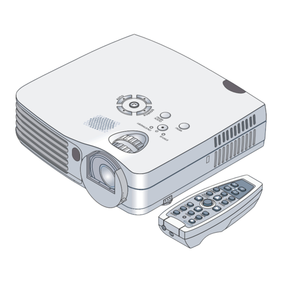
Page 16: Names Of The Main Unit Parts
Names of the Main Unit Parts Speaker Zoom ring [E-19] Ventilation slots Exhaust vents Built-in security slot Remote control sensor [E-8] Focus ring [E-20] Lens Adjuster button [E-20] Lens cover (Also on opposite side) Lamp cover [E-53] Rear adjuster [E-20] Front adjusters [E-20]... - Page 17 Names of the Main Unit Parts ON/STANDBY indicator Buttons used in menu and [E-16, quick menu operations [E-27, STATUS indicator [E-16, STATUS ON/STANDBY AUTO button [E-21] ON/STANDBY button [E-16] QUICK SELECT ( ) buttons MENU MENU MENU button [E-28] ENTER button [E-17] QUICK MENU button [E-27] SOURCE button [E-21] Remote control sensor [E-8]...
-
Page 18: Names Of The Remote Control Parts
Names of the Remote Control Parts Refer to the description (and diagram) for the remote control unit included with your projector. Infrared transmitter [E-8] Laser transmitter [E-25] L-CLICK button [E-26] LASER button [E-25] STANDBY button [E-16, (Turns the laser point on and off) This button is used to switch ON the power and set the unit to the STANDBY... -
Page 19: Preparing The Remote Control
Preparing the Remote Control Inserting the Batteries Install the supplied batteries to use the remote control. Slide the battery compartment Insert the batteries to match (A) Leaving a little space in the front, cover (located on the bottom of the "+" and "–" as indicated in- close the lid, (B) then with the back the remote control) and pull off. -
Page 20: The Procedure Up To Projecting To The Screen
The Procedure Up to Projecting to the Screen Perform setup adjustments in the following order. Position the projector Determine the locations to set up the screen and the projector. See “Placement Guide” on Page E-10. Connect your equipment to the projector When making connections with the personal computer’s RGB connector, see “Connections with Personal Computer”... -
Page 21: Placement Guide
Placement Guide • Use this information as a guide to find out about the screen size when the projector is placed at a certain location, or to find out the approximate size of a screen that will be required. • The projection distance over which focussing is adjustable is 1.20 m (3.9 feet) to 14.17 m (46.50 feet). The projector should be placed within this range. -
Page 22: Connecting Personal Computers And Video Equipment
Connecting Personal Computers and Video Equipment Connecting this unit with a personal computer permits presentation data to be projected as a large screen display at conferences, lectures, and on other occasions. Connecting this unit to a DVD player or other video equipment source in combination with an audio/video amplifier and speaker system will allow you to enjoy convincing home theater. -
Page 23: To Output The External Output Signal Of A Notebook Computer
All computers Fn + F5 SONY All computers Fn + F7 SOTEC All computers Fn + F3–F5 TOSHIBA All computers Fn + F5 Victor All computers Fn + F10 Note: Table information is current to December 2003. Note: When the liquid crystal display of the notebook computer and the projector are displayed at the same time, the projected image might not be correct even though the liquid crystal display shows a correct indication. -
Page 24: Connections With Video And S-Video Signals
Connecting Personal Computers and Video Equipment Connections with Video and S-Video Signals Video Equipment with VIDEO Connectors • Connect to the projector’s VIDEO connector by using a commercially available video cable. • The input setting of the VIDEO connector has been set to “Auto” at the factory; however, if the projector does not project, change the input setting to “Your Country’s Television Broadcast System”... -
Page 25: Connections With Component Signals
Connecting Personal Computers and Video Equipment Connections with Component Signals When the Video Equipment Has a YCbCr Connector or YPbPr Connector • The projector has been set to “Auto” at the factory; however, if it does not project, change the input setting to “Component” by using the menu sequence of [Setup] →... -
Page 26: Connections With The Audio Jack
Connecting Personal Computers and Video Equipment Connections with the AUDIO Jack * Connect to the projector’s AUDIO jack by using a commercially available audio cable. If the other device has an RCA phono type audio jack, connect via a commercially available audio converter cable. * The built-in speaker of the projector provides monaural audio. -
Page 27: Power Cord Connections And Switching The Power On/Off
Power Cord Connections and Switching the Power On/Off There is an order in which the power cord is connected and the power is switched on/off. Operating Connect the AC IN connector of the projector and the well outlet by using the supplied power cord. The ON/STANDBY indicator will light in amber, and the unit will enter the standby mode. - Page 28 Power Cord Connections and Switching the Power On/Off When [Menu Language Select] is Displayed Upon Switching On the Power The first time the power is switched on after purchase, [Menu Lan- guage Select] will be displayed. Follow the procedure described be- low and select the display language of the projector.
-
Page 29: Finishing
Power Cord Connections and Switching the Power On/Off Finishing Switch off the power of the connected equip- ment Switch off the power of the projector Press the ON/STANDBY button. STANDBY LASER STATUS ON/STANDBY VIDEO AUTO (button on main unit) MENU QUICK The [Power Off] display appears. -
Page 30: Adjustment Of The Projection Screen
Adjustment of the Projection Screen Switch on the power of the connected equipment and make the adjustments with the video signal being input to the projector. Adjustment of the Projection Screen Turn the zoom ring to adjust the screen size of the projection image. When the adjustment range is not enough, you may move the projector to the rear or forward. -
Page 31: Making Adjustments With The Adjusters
Adjustment of the Projection Screen Turn the focus ring and adjust the focus of the screen Focus ring Making Adjustments with the Adjusters Raising the projection image While viewing the projection image, (1) press and hold the front adjuster buttons located at the left and right and, (2) raise the projector to align the image with the screen, ( 1 ) then release your fingers. -
Page 32: General Operation
General Operation This section describes the use of direct operation with the main unit or remote control buttons. For information about operation using the menu, see “Menu Operation Method” on Page E-28 and the various items on Pages E-35 to E-48. Input Selection This operation selects the input signal to be projected. -
Page 33: Freezing A Moving Picture
General Operation Freezing a Moving Picture This function is used to stop and view a moving picture. Note that the input image continues to advance even though the picture there is a still picture STANDBY LASER condition. VIDEO AUTO A press of the FREEZE button changes the screen to a still picture. A MENU QUICK further press returns the screen to a moving picture. -
Page 34: Enlargement Of The Image And Video Movement
General Operation Enlargement of the Image and Video Movement This function digitally enlarges the personal computer image and video image. STANDBY LASER (1) Press the ZOOM button to enlarge the image. VIDEO AUTO The zoom display appears when the ZOOM button is pressed. MENU QUICK R-CLICK/... -
Page 35: Using The Presentation Timer
General Operation Using the Presentation Timer The presentation is given while checking the timer displayed on the screen. The gauge display allows the remaining time to be known at STANDBY LASER a glance. VIDEO AUTO MENU QUICK (1) Press the TIMER button to show the settings display. The display will close when an operation has not been made for about 10 seconds. -
Page 36: Using The Laser Pointer
General Operation Using the Laser Pointer The remote control unit’s laser pointer can be used to point to the section currently being explained, making presenta- tions more effective. CAUTION Do not look at the laser pointer’s light source. Be sure to heed the following. Pointing the laser beam at the eyes could lead to reduced vision or vision impairment. -
Page 37: Performing Mouse Operations On The Computer With The Remote Control Unit
General Operation Performing Mouse Operations on the Computer with the Remote Control Unit When a computer and the projector are connected, mouse operations can be performed on the computer by using the projector’s remote control unit. When projecting images from the computer, the projector can be operated and mouse operations on the computer performed with the same remote control unit, making for efficient presentations. -
Page 38: Using The Quick Menu
General Operation Using the Quick Menu This function permits frequently used adjustments to be performed quickly. Note that the Quick Menu will not be displayed unless the signal of the con- nected equipment is input. Select the input that you wish to adjust. Main unit operation (1) Press the QUICK MENU button to display the quick adjustment display. -
Page 39: Menu Operation Method
Menu Operation Method • For information about a menu function, adjustment, or setting, see one of the pages containing such descriptions. • Adjustments and settings are made by projecting an image and adjusting to an optimum condition. • To return the various items that have been changed via the menu to their standard values (i.e., default values at time of shipping from the factory), see “Factory Default”... - Page 40 Menu Operation Method Menu Screen Names and Functions Menu Name Cursor (Deep Blue) This is the title of the menu. This permits setting/adjustment of the There is a change to the title screen item located at the cursor position. when the menu is selected. The cursor moves to the selected menu name.
-
Page 41: Performing Menu Operations
Menu Operation Method Performing Menu Operations • Only “Setup”, “Options” and “Info.” can be selected when no signal is being input. • The menu display will close if, after pressing a button, the next button operation is not made within 30 seconds. •... - Page 42 Menu Operation Method Displaying the Cursor Press the SELECT button to display the item name selection cursor. STANDBY LASER VIDEO AUTO MENU QUICK This condition al- lows selection of the R-CLICK/ ENTER CANCEL item name. FREEZE MUTE TIMER Selection of the Item Name Press the SELECT ( ) button to align the cursor with the item name STANDBY...
- Page 43 Menu Operation Method Closing the Menu Press the MENU button and close the menu display STANDBY LASER VIDEO AUTO MENU QUICK R-CLICK/ ENTER CANCEL FREEZE MUTE TIMER Selecting Another Menu Name with Remote Control Operation When a sub menu is displayed, press the CANCEL but- ton and close the sub menu.
-
Page 44: List Of Item Names Offering Input Selection And Adjustments/Settings
Menu Operation Method List of Item Names Offering Input Selection and Adjustments/Settings The item names that can be adjusted/set will differ depending on the input signal. [Example of Menu Display Items at the Time of Input Signal RGB Selection] Sub Menu Menu name Item Name Reference... -
Page 45: Menu Name
Menu Operation Method Sub Menu Menu name Item Name Reference Item Name Page Setup E-42 Auto Source E-42 Auto Power Off E-43 Menu Position Lamp Mode E-43 Input Format E-44 E-44 Video E-44 S-Video E-44 Presentation Timer Option Language E-45 E-45 On Screen Background... -
Page 46: Image
Image • Perform this operation while projecting the picture for which the adjustment/setting will be made. • Select the menu name “Image”. See “Menu Operation Method” on Page E-28 for information about performing menu operations. The item name display will differ depending on the input signal. -
Page 47: Reset
Image Fine Picture Adjust this when the picture shows a lack of color fidelity or flickering. Select the “Fine Picture” item name and adjust with the SELECT ( ) but- tons so that the lack of color fidelity or the flickering disappears. H Position Adjust this when the picture is shifted to the left or right. -
Page 48: Color
Color • Do the following operation while displaying the image you want to adjust or set. • Select the menu name “Color”. See “Menu Operation Method” on Page E-28 for information about performing menu operations. The item name display will differ depending on the input signal. -
Page 49: Color Temp
Color Color Temp. The screen color is affected by the color of the illumination and other extraneous light. This function adjusts the white, which is the reference color for video equipment, and improves the quality of color reproduction. Adjustment can also be used to enhance skin colors. Select the item name “Color Temp.”... -
Page 50: White Balance
Color White Balance This function adjusts the black level and the white level of the analog RGB input signal to suit the personal computer. Select the item name [White Balance] and press the ENTER button. The display will change to [Input Black Signal]. The screen background color of the connected personal computer will be set to black. -
Page 51: View
View • Perform this operation while projecting the picture for which the adjustment/setting will be made. • Select the menu name “View”. See “Menu Operation Method” on Page E-28 for information about performing menu operations. The item name display will differ depending on the input signal. -
Page 52: Horizontal Flip
View Horizontal Flip In selecting the method of projecting to the screen, these functions are set when the projector is in a rear screen installation. Select the item name “Horizontal Flip” and select the setting contents with the SELECT ( ) buttons. -
Page 53: Setup
Setup • Select menu name “Setup”. See “Menu Operation Method” on Page E-28 for information about performing menu operations. The item name display will differ depending on the input signal. See “List of Item Names Offering Input Selection and Adjustments/Settings” on Page E-33. Auto Source The Auto Source function automatically detects the input signal when the power is switched on and when the input is switched. -
Page 54: Menu Position
Setup Menu Position This function sets the display position of the menu. Select item name “Menu Position” and select the setting contents with the SELECT ( ) buttons....Displays on the left side ..... Displays on the right side Lamp Mode Use this if the picture is projected on a small screen and the picture is too bright or when projecting images in dark rooms. -
Page 55: Input Format
Setup Input Format This function is used in setting the input signals of the input connec- tors. Normally, this should be set to Auto. When identification is not possible with Auto, make the setting. Select the item name “Input Format”, press the ENTER button, and the sub menu will open. -
Page 56: Language
Option • Select menu name “Option”. See “Menu Operation Method” on Page E-28 for information about performing menu operations. The item name display will differ depending on the input signal. See “List of Item Names Offering Input Selection and Adjustments/Settings” on Page E-33. Language This function sets the language that is displayed on screen in the messages and menu displays. -
Page 57: Startup Screen
Select item name “Startup Screen” and select the setting contents with the SELECT ( ) buttons. Logo ... Displays the logo. Blank ..Does not display the logo. Note: When “Logo” is selected at the startup screen, the “TOSHIBA” logo is dis- played. E-46... -
Page 58: Info
Press the CANCEL button to return to the menu. Display Contents: Projector model, firmware version, and the internet home page ad- dress of TOSHIBA Corp. Factory Default This function returns the adjustments and settings of all the in- put sources to the standard factory default values. -
Page 59: Resolution / Frequency
Info. Resolution / Frequency This function displays the resolution and frequency of the detected in- put signal. Lamp Timer This displays the lamp timer. This projector has an Eco mode function. The lamp life will differ between Normal mode and Eco mode. Lamp Life Use only in Normal mode: approx.2000 hours Use only in Eco mode: approx.2500 hours... -
Page 60: When An Indicator Is Lit Or Flashing
When an Indicator is Lit or Flashing The indicators on the projector’s control panel light or flash to STATUS indicator notify of problems, as described below. An indicator is also used to notify you of the currently set power mode. See “Power Cord Connections and Switching the Power On/Off”... -
Page 61: Troubleshooting
Troubleshooting Check the following matters before requesting servicing. Reference Problem Check Page • Is the power cord plugged into a power outlet? Power does not turn on E-16 • Is the lamp cover properly mounted? E-54 • Is the projector’s temperature high? To protect the projector, the power can- E-49 not be turned on when the projector’s temperature is abnormally high. -
Page 62: Cleaning
Cleaning • Be certain to disconnect the power plug from the power outlet before cleaning. • Do not spray or otherwise expose the projector, lens, or screen to volatile substances such as insecticides. Do not leave rubber or vinyl products in contact with the projector for long periods. Doing so could cause them to undergo qualitative changes or the coatings may peel, etc. -
Page 63: Replacing The Lamp Cartridge
Replacing the Lamp Cartridge • The lamp that is used as a light source in the projector has a limited service life. The rated service life of the lamp is about 2000 hours (when used in normal mode only). This could be shortened depending on conditions of use and other factors. - Page 64 Replacing the Lamp Cartridge Preparations: Turning the projector upside-down on top of a soft cloth, etc., so that it does not get scratched makes it easier to replace the lamp cartridge. Turn the projector right-side up after replacing the lamp cartridge. Unplug the power cord.
- Page 65 Replacing the Lamp Cartridge Mount the new lamp cartridge. (2) Turn the lamp cartridge’s two screws clockwise to tighten (1) Push the lamp cartridge in slowly. (Line it up with the screw holes in the projector.) them. Mount the lamp cover. (2) Turn the lamp cover’s screw clockwise to tighten it.
-
Page 66: Specifications
Specifications Model TDP-P7 Optical Method of projection : DLP™ (single chip DMD) 0.7 inches 1024 768 dots Lamp 130 W high pressure mercury lamp Projection lens : Manual zoom ( 1.2), Manual focus F = 2.6 – 2.9, f = 27.5 – 33.0 mm Image size Minimum 26 inch (at projection distance of 1.20 m / 3.9 feet telephoto) Maximum 300 inch (at projection distance of 11.81 m / 38.76 feet wide) -
Page 67: Table Of Supported Frequency
Table of Supported Frequency The projector automatically identifies the signal input from the computer and selects the optimum resolution as shown on the table below. Manual adjustments may be required for some input signals. See “Picture Adj. / Fine Picture / H Position / V Position” on page E-35, Frequency Signal... -
Page 68: Cabinet Dimensions
Cabinet Dimensions 186 (7.3) 46 (1.8) STATUS ON/STANDBY QUICK MENU MENU Unit: mm (inch) E-57...
Need help?
Do you have a question about the TDP-P7U and is the answer not in the manual?
Questions and answers