Table of Contents
Advertisement
Quick Links
Advertisement
Table of Contents

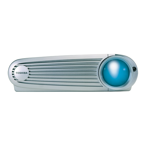
Related Manuals for Toshiba TDP-P4


Summary of Contents for Toshiba TDP-P4
- Page 2 SAFETY PRECAUTION WARNING: Service should not be attempted by anyone unfamiliar with the necessary precautions on this projector. The following are the necessary precautions to be observed before servicing this chassis. 1 . An isolation Transformer should be connected in the power line between the projector and the AC Iine before any service is performed on the projector.
-
Page 3: Table Of Contents
Downloading the software to your computer.............. 63 Installing the Software on the Computer..............65 Upgrading the TDP-P4 software ................66 Performing Functional Tests on the TDP-P4 ............71 Troubleshooting ......................76 Parts Lists........................96 Case Parts Exploded View ..................96 Component Exploded View .................. -
Page 4: Safety Precautions
The exclamation point within an WARNING: Changes or modifications made to this equipment, not expressly approved by equilateral triangle is intended to Toshiba, or parties authorized by Toshiba, could void the user's authority to operate alert the user to the presence of the equipment. -
Page 5: Important Safety Instructions
IMPORTANT SAFETY INSTRUCTIONS CAUTION: PLEASE READ AND OBSERVE 1. Read Owner's Manual 3. Source of Light ALLWARNINGS AND After unpacking this product, read the Do not look into the lens while the lamp INSTRUCTIONS GIVEN IN THIS owner's manual carefully, and follow all is on. - Page 6 IMPORTANT SAFETY INSTRUCTIONS Object and Liquid Entry 13. Stack Inhibited Accessories Never push objects of any kind into this Do not stack other equipment on this Do not place this product on an unstable product through openings as they may product or do not place this product on the cart, stand, tripod, bracket, or table.
-
Page 7: Parts Replacement
To see exploded views of the case parts, major components and optical engine, see page 96. Controller ECA 510-1544-xx Ballast 526-0090-xx Optical engine Lamp module 530-0120-xx SP-LAMP-LP1 Front fan 526-0065-xx TDP-P4 Service Manual... - Page 8 (fastened to the optical engine below the controller ECA) 526-0071-xx Also part of optical engine I/O EMI shield 330-0700-xx Lamp fan 526-0076-xx Also part of optical engine Power supply 510-0889-xx Power supply insulator (located between power supply and bottom case.) 510-0889-xx TDP-P4 Service Manual...
-
Page 9: Focus And Zoom Rings
To access the zoom ring, remove the optical engine (see page 45) Turn the optical engine upside down on a soft surface. CAUTION The optical engine in the TDP-P4 has an exposed glass color wheel. Take extreme care when handling the engine. - Page 10 Tighten the screws to 2 in.-lbs. (.226 N m). ♦ Snap the focus ring around the front of the lens, making sure that the three recesses in the focus ring engage the three tabs on the sides of the lens. TDP-P4 Service Manual...
-
Page 11: Front Bezel
Place the projector on its side to release the front bezel latch. Use your finger or a screwdriver to slide the latch tab toward the rear of the projector. Hold the latch in position and slide the bezel slightly toward the side of the projector opposite the lens. TDP-P4 Service Manual... - Page 12 When you replace the front bezel, make sure that the hooks on the bezel properly engage the pins on the top and bottom cases. Slide the bezel toward the lens until the latch locks the bezel in position. TDP-P4 Service Manual...
-
Page 13: Lamp Module
Use a flat-blade screwdriver to loosen the captive screw that fastens the lamp module to the optical engine. You don't need to remove the screw. Pull the release latch at the lower left side of the lamp module outward to disengage the connection between the lamp module and the ballast. TDP-P4 Service Manual... - Page 14 ♦ Push the release latch at the lower left side of the lamp module inward to engage the connection between the lamp module and the ballast. ♦ Tighten the captive screw to 3 in.-lbs. (.339 N m). TDP-P4 Service Manual...
-
Page 15: Rear Bezel
Use a T-8 Torx driver to remove the M2.5x6 Torx screw from the rear bezel. Gently pry the rear bezel away from the projector. You may need to use a small screwdriver. Do not pry around the edge of the bezel. Instead, reach in between the power button and the bezel. TDP-P4 Service Manual... - Page 16 Replace the right side of the bezel first. Then press the left side into place. The bezel should fit flush with the top and bottom cases. ♦ Fasten the bezel to the projector with the M2.5x6 screw. Tighten the screws to 3 in.-lbs. (.338 N m) TDP-P4 Service Manual...
-
Page 17: Rubber Feet
To replace a rubber foot, peel the protective paper off the bottom of the foot. Then press the foot into the recess in the bottom case. If you need to remove a portion of an old rubber foot, gently pry it away from the bottom case. TDP-P4 Service Manual... -
Page 18: Top Case
Front bezel (see page 11) Rear bezel (see page 15) Place the unit upside-down on the bench and detach the keypad cable from its ZIF connector on the controller ECA. The connector is adjacent to the I/O panel. TDP-P4 Service Manual... - Page 19 Use a T-8 Torx driver to remove the M2.5x8 Torx screw that secures the top case to the projector. Carefully turn the unit over and lift the top case away from the projector. If you are replacing the top case, remove the keypad. (see page 21) TDP-P4 Service Manual...
- Page 20 Check the ZIF connector latch after you insert the cable to make sure it is locked. ♦ Secure the top case to the bottom case with the M2.5x8 Torx screw. Tighten the screw to 3 in.-lbs. (.339 N m). TDP-P4 Service Manual...
-
Page 21: Keypad
On the inside of the top case, use tweezers or small needle nose pliers to press out the three tabs that hold the keypad to the top case. Make sure to hold the keypad in from the other side when you release the tabs. TDP-P4 Service Manual... - Page 22 Place the keypad into its recess in the top case, being careful to avoid kinking the cable. Then gently press the keypad into place. Take care not to bend the tabs on the back of the keypad. TDP-P4 Service Manual...
-
Page 23: I/O Emi Shield
Top case (see page 18) Use a 3/16 inch nut driver to remove the #4-40 jack screws from both sides of the M1 connector. Pull the I/O shield away from the M1 and video connectors on the controller ECA. TDP-P4 Service Manual... - Page 24 The contact fingers at the top of the I/O shield should contact the top case when it's replaced. ♦ Fasten the I/O shield to the M1 connector on the controller ECA using the two jack screws. Tighten the jack screws to 4 in.-lbs. (.451 N m). TDP-P4 Service Manual...
-
Page 25: Lamp Sync Cable
Lamp module (see page 13) Unplug the lamp sync cable from connector J504 on the controller ECA. CAUTION! Make you do not stretch the cables inside the connectors. Use a needle-nose pliers or tweezers to unplug the connectors. TDP-P4 Service Manual... - Page 26 Unplug the power supply/ballast cable from its connector on the ballast. Remove the screw that fastens the ballast to the bottom case TDP-P4 Service Manual...
- Page 27 Note that the ballast is still attached to the power supply with a cable. Place the ballast on the work surface next to the bottom case. Use a tweezers or small pick to work the lamp sync cable connector loose. Take care not to damage the circuit board. TDP-P4 Service Manual...
- Page 28 Note that the two connectors on the lamp sync cable are different. The connector with the small holes plugs into the ballast ♦ To plug in the cable, align the holes on the cable connector with the pins on the ballast connector. Then press the connector into place. TDP-P4 Service Manual...
-
Page 29: Front Fan
Remove the following items: Front bezel (see page 11) Rear bezel (see page 15) Top case (see page 18 Unplug the fan cable from the controller ECA at connector J500. Lift the fan from its recess in the bottom case. TDP-P4 Service Manual... - Page 30 ♦ Position the fan so that it rests in the guide slots in the bottom case. ♦ Reconnect the cable to the controller ECA. TDP-P4 Service Manual...
-
Page 31: Lamp Fan
Lamp fan cable at connector J502 Optical engine blower at connector J503 Lamp sync cable at connector J504 Power supply cable at connector P2 (below the lamp sync and blower connectors) TDP-P4 Service Manual... - Page 32 Carefully twist the fan counterclockwise to allow it to clear the optical engine chassis and the ballast assembly during removal. The fan fits into a recess in the ballast. By twisting the fan slightly you can clear both the ballast and the controller ECA. Lift the fan out of the projector. TDP-P4 Service Manual...
- Page 33 Position the fan against the bracket on the optical engine chassis. ♦ Replace the M2.5x6 screw that secures the fan to the optical engine chassis. Tighten the screw to 3 in.-lbs. (.339 N m). ♦ Reconnect the cables to the controller ECA. TDP-P4 Service Manual...
-
Page 34: Controller Eca
Remove the following items: Front bezel (see page 11) Rear bezel (see page 15) Top case (see page18) Unplug the cables from the following connectors on the controller ECA: TDP-P4 Service Manual... - Page 35 Use a T-8 Torx driver to remove the six M2.5x6 screws that attach the controller ECA stack to the bottom case and optical engine. Carefully lift the controller ECA upward to disengage the connector on the bottom side from the optical engine. Lift from the center of the board, as indicated below. TDP-P4 Service Manual...
- Page 36 ECA down firmly to ensure that they securely engage. ♦ Fasten the controller ECA to the optical engine and bottom case with the six M2.5x6 screws. Tighten the screws to 3 in.-lbs. (.339 N m). ♦ Reconnect all cables to the controller ECA. TDP-P4 Service Manual...
-
Page 37: Ballast
Top case (see page 18) Lamp module (see page 13) Controller ECA (see page 34) Lamp fan (see page 31) Squeeze the tab on the side of the power supply cable connector and unplug it from the ballast assembly. TDP-P4 Service Manual... - Page 38 Unplug the ballast connector at the power supply. Use a Torx T-8 screwdriver to remove the M2.5x6 screw that attaches the ballast assembly to the bottom case. TDP-P4 Service Manual...
- Page 39 Lift the ballast assembly from the rear side to disengage the hook on the front from the eye in the bottom case. TDP-P4 Service Manual...
- Page 40 CAUTION Avoid damage to the plastic insulation on the side of the ballast assembly when you install it in the bottom case. The insulation should have no holes or tears. If holes or tears are apparent, do not use the ballast assembly. TDP-P4 Service Manual...
-
Page 41: Front Bezel Latch
Front bezel (see page 11) Lamp module (see page13) Rear bezel (see page 15) Top case (see page 18) Squeeze the tab on the side of the power supply cable connector and unplug it from the ballast assembly. TDP-P4 Service Manual... - Page 42 Lift the ballast from the rear side to disengage the hook on the front from the eye in the bottom case. Note that the ballast is still attached to the power supply with a cable. TDP-P4 Service Manual...
- Page 43 Use a Phillips screwdriver to remove the M2.5x6 screw and washer from the front bezel latch. TDP-P4 Service Manual...
- Page 44 The spring should be fully seated on the actuator and rest against the tang in the bottom case. ♦ Replace the M2.5x6 screw and washer that secure the front bezel latch in the bottom case. ♦ Check the operation of the front bezel latch before you assemble the projector. TDP-P4 Service Manual...
-
Page 45: Optical Engine
Controller ECA (see page 34) CAUTION The color wheel is exposed in the TDP-P4 engine. Take extreme care not to bump it with a tool or press against it because it is very delicate. A broken color wheel requires engine replacement. - Page 46 Use a T-8 Torx driver to remove the two M2.5x6 Torx screws that attach the optical engine to the bottom case. Carefully lift the optical engine up and out of the bottom case. Take care where you pick the engine up. Below are some good places to grasp the optical engine. TDP-P4 Service Manual...
- Page 47 Ensure that the gasket is in place on the top of the optical engine to insulate it against the controller ECA. ♦ Tighten the two M2.5x6 screws that secure the engine to the bottom case to 3 in.-lbs. (.338 N m). TDP-P4 Service Manual...
- Page 48 The clamshell plastic case that comes with each new engine is designed to protect the engine and color wheel during shipping and storage. When you replace an optical engine in the TDP-P4, you must put the old engine in the clamshell case in which the new engine was shipped.
- Page 49 Close the top of the case over the engine and snap the corners together. TDP-P4 Service Manual...
-
Page 50: Elevator Assembly
Gently pry one of the two tabs on the elevator housing away from the stops at the upper end of the elevator shaft, allowing the shaft to fall through the housing. Take care when prying the tabs. TDP-P4 Service Manual... - Page 51 Slide the elevator housing toward the center of the projector to disengage two tabs from slots in the bottom case. Then remove the housing. Once the housing is out, you can lift the actuator out of the bottom case. TDP-P4 Service Manual...
- Page 52 Hold the actuator and housing together as you replace them in the bottom case. Note how the actuator end fits into the housing. ♦ Fasten the elevator housing to the bottom case with the M2.5x6 screw. Tighten the screw to 3 in.-lbs. (.338 N m). TDP-P4 Service Manual...
-
Page 53: Engine Blower
Front bezel (see page 11) Rear bezel (see page 15) Top case (see page 18) Controller ECA (see page 34) Optical engine (see page 45) Use a small flat-blade screwdriver to gently pry the blower away from the optical engine chassis. TDP-P4 Service Manual... - Page 54 CAUTION Pry carefully to avoid breaking the optical engine chassis or damaging the color wheel. The glass color wheel is exposed in the TDP-P4, and can be easily broken if care is not taken. A broken color wheel requires optical engine replacement.
-
Page 55: Power Supply
Lamp module (see page 13) Rear bezel (see page 15) Top case (see page 18) Controller ECA (see page 34) Optical engine (see page 45) Open the cable clip attached to the bottom case between the power supply and ballast. TDP-P4 Service Manual... - Page 56 Squeeze the tab on the side of the power supply cable connector and unplug it from the ballast assembly. Unplug the ballast connector at the power supply. TDP-P4 Service Manual...
- Page 57 Assembly Notes ♦ Before replacing the power supply insulator, make sure it is in good condition. There should be no holes or tears in the top or bottom. If you observe damage, replace the insulator. TDP-P4 Service Manual...
- Page 58 This allows the insulator to wrap around the post near the rear corner of the bottom case. ♦ Fasten the power supply to the bottom case with the M2.5x6 screws. Tighten each screw to 3 in.-lbs. (.338 N m) TDP-P4 Service Manual...
-
Page 59: Bottom Case
Top case (see page 18) Controller ECA (see page 34) Optical engine (see page 45) Power supply (see page 55) Power supply insulator (see page 57) Ballast (see page 37) You are left with the bottom case. TDP-P4 Service Manual... - Page 60 The certification label (020-1077-xx) fits into the recessed area on the outside of the bottom case. If you need to replace it, be sure to remove the serial number label (above) and adhere it to the new certification label. TDP-P4 Service Manual...
- Page 61 While holding the resync button down, press the menu button for 10 seconds. To verify that the counter was reset, press the menu button, then navigate to the Status menu. The lamp counter is at the top of the list. TDP-P4 Service Manual...
- Page 62 Fasteners Below is a list of the fasteners included in the fastener kit (802-0025-xx) for the TDP-P4 projector. You'll also find the suggested torque settings for each fastener. Fastener Application Torque M2.5x6 Torx SEM Power supply (4), ballast (1), optical engine (2), 3 in.-lbs.
-
Page 63: Software Upgrades
When you click the Download Now button on the Software page, the File Download dialog box appears. NOTE The illustrations below refer to version 3.0 of the TDP-P4 software. The version of the software you download may be different. In the File Download box, select Save This Program To Disk option, then click OK. - Page 64 Once you install the software files, you won’t need the .EXE file you download. You may want to save it in a temporary folder. The file downloads to your computer’s hard drive. Now you're ready to install the software on the computer. See page 65 to install the software on the computer. TDP-P4 Service Manual...
-
Page 65: Installing The Software On The Computer
In Windows Explorer, locate the .EXE file that contains the upgrade files. Double-click the file to extract the contents. The filename P4v30.exe means that this is version 3.0 of the system software for the TDP-P4. The version number changes each time the software is updated. -
Page 66: Upgrading The Tdp-P4 Software
Upgrading the TDP-P4 software To upgrade the TDP-P4 software, you need the M1-A cable (210-0185-xx) that ships with the projector. SPECIAL NOTE The computer you use to upgrade the software on the TDP-P4 must run Windows 98 and must have an available USB connector. - Page 67 The FlashUSB dialog box opens, ready to begin the upgrade process. Click the Select Files button in the FlashUSB dialog box. In the Open dialog box, select all the HEX files, then click Open. TDP-P4 Service Manual...
- Page 68 While holding the buttons down, power up the projector. NOTE If you're upgrading a TDP-P4 for the first time, you may see Windows 98 New Hardware Wizard. Follow the instructions, then continue with this procedure. Hold the keys down firmly after you power up the projector. The projector should go to ‘load state’, where the fans are running and the green LED glows, but the lamp does not light.
- Page 69 In the FlashUSB dialog box, click the Download button. The software begins downloading to the projector. The process takes several minutes. When the download is complete, the FlashUSB dialog box closes, and the projector lamp lights. The Toshiba splash screen appears. TDP-P4 Service Manual...
- Page 70 23 = data configuration v2.3 26 = GUI code v2.6 30 = ROM code v3.0 The version number you see should match the series of version numbers for each HEX file in the file you downloaded from the InFocus/Toshiba web site. TDP-P4 Service Manual...
-
Page 71: Performing Functional Tests On The Tdp-P4
Make sure the video player has an S-video Out port and cables. The player should also have a Composite video output port (RCA). Toshiba strongly suggests you use a DVD player to test the video quality. DVD players reproduce colors better and project sharper images. - Page 72 90° angle to Verify cosmetics. the wall. Composite video from video source Verify that the video automatically synchronizes. On the keypad, press the Verify there is no distortion, noise or other abnormalities. Video button. TDP-P4 Service Manual...
- Page 73 Verify that the images project synchronize properly through the following computer images. These will inputs: confirm that the computer M1 Analog input works properly, and will M1 Digital test image quality. Press the Computer button on the keypad. TDP-P4 Service Manual...
- Page 74 Image #2: Color Ramp Project the Color Ramp image. Verify there are no missing parts of the ramp. Verify that the bars are not flashing. Verify that the transitions from light to dark are smooth and gradual. TDP-P4 Service Manual...
- Page 75 Verify that the image synchronizes. On the Display menu, select Reset All. Power Down Verify unit is powered off before disconnecting cables. After all tests are complete turn the power off and disconnect all cables. Attach the lens cap. TDP-P4 Service Manual...
-
Page 76: Troubleshooting
No menu (page 88) ♦ A system/controller ECA block diagram (page 89) ♦ Voltage check points on the controller ECA (page 90) ♦ Powering up the projector with the top case removed (page 91) ♦ Checking fan operation (page 93) TDP-P4 Service Manual... - Page 77 What is the problem? No signs of No lamp. Fans Lamp or projector power. are running. shuts off after No fans, no LED running a short period of time. (page 79) (page 78) (page 81) TDP-P4 Service Manual...
- Page 78 No signs of power. No fans, no LED. Use a known good power cord. Does the Replace projector power power cord. Replace power supply. (page 55) TDP-P4 Service Manual...
- Page 79 Replace the lamp module Confirm that the color wheel cable is connected If the color wheel cable is disconnected, the (page 95) lamp will light and the fans will start briefly before shutting down. Go to next page. TDP-P4 Service Manual...
- Page 80 Color wheel failure is almost always Front Fan due to bad voltage from the (page 53) Engine Blower controller board. Does the Replace the Replace Controller ECA. lamp light and optical engine (bad voltage to fan) stay lit? (page 45) (page 34) TDP-P4 Service Manual...
- Page 81 Substitute a good controller ECA. (page 34) Run the projector long enough to warm up or shut down. Does the Replace the projector run controller ECA. properly? Replace the ballast (bad thermal switch). (page 37) TDP-P4 Service Manual...
- Page 82 Bad or missing tint or color Vertical or (page 85) Missing logo, VGA, composite horizontal lines. video, or S-video Sparkley picture. Distorted image, noisy, rolling, Clusters of dark torn, frozen, 'plaid', repeated, pixels. or shifted image (page 83) (page 84) TDP-P4 Service Manual...
- Page 83 No image. Vertical lines. Horizontal lines. Sparkly picture. Clusters of dark pixels. Replace the controller ECA. (page 34) Is the image correct? Replace the optical engine. (page 45) TDP-P4 Service Manual...
- Page 84 Missing startup screen, VGA, composite video or S-video. Distorted image, excess noise, rolling image, torn image, frozen image, 'plaid' image, repeated single image, or shifted image. Make sure cables are good. Is the image correct? Replace the controller ECA. (page 34) TDP-P4 Service Manual (page 32)
- Page 85 The lamp takes about 90 seconds to achieve full brightness. Is the image Replace the lamp. brighter? Substitute a known good controller ECA. (page 34) Is the image Replace the controller ECA. brighter? Replace the optical engine. (page 45) TDP-P4 Service Manual...
- Page 86 Troubleshooting Remote Problems Infrared remote problem Use known good batteries in the remote. Does the remote work? Use a known good remote with the projector. Replace the Does the remote. remote work? Replace the controller ECA. (page 34) TDP-P4 Service Manual...
- Page 87 (page 21) Does the Does the Replace the Replace the projector respond projector respond controller ECA. keypad. to key presses? to key presses? (page 21) (page 34) Replace the Replace the keypad. controller ECA. (page 34) (page 21) TDP-P4 Service Manual...
- Page 88 Does the menu doesn't, go to doesn't, go to appear? Keypad problems. Remote problems. (page 87) (page 86) Flash or reflash the latest software into the projector. Does the menu appear? Replace the controller ECA. (page 34) TDP-P4 Service Manual...
- Page 89 Block Diagram TDP-P4 Service Manual...
- Page 90 Controller voltages TDP-P4 Service Manual...
- Page 91 Rear Bezel (see page 15) Top case (see page 18) Once the top case is off, you have access to the interlock switch on the front of the ballast. Defeat the interlock switch with a nylon screwdriver or spacer. TDP-P4 Service Manual...
- Page 92 Power up the projector TDP-P4 Service Manual...
- Page 93 Top case (see page 18) Lamp module (see page 13) Once the top case is off, you have access to the interlock switch on the front of the ballast. Defeat the interlock switch with a nylon screwdriver or spacer. TDP-P4 Service Manual...
- Page 94 Plug the projector in and turn it on. The fans and blower start up and run for 2- 3 seconds, then shut down (because there is no lamp installed). This is time enough to make sure the fans and blower run properly. TDP-P4 Service Manual...
- Page 95 The cable should not move. If the cable moves in and out or side to side in the connector, it probably is not making good contact. Release the latch, re-insert the ribbon cable, then tighten the latch. TDP-P4 Service Manual...
-
Page 96: Parts Lists
Keypad 526-0089-xx Top case 526-0811-xx Rear bezel 505-0901-xx Elevator Assembly 505-0906-xx Also part of bottom case. Bottom case 505-0812-xx Zoom ring 505-0921-xx Front bezel latch 505-0918-xx Also part of bottom case. Focus ring 505-0874-xx Front bezel 505-0814-xx TDP-P4 Service Manual... -
Page 97: Component Exploded View
Controller ECA 510-1544-xx Optical engine 5050920xx Power supply Ballast 510-1506-xx 526-0090-xx Power supply insulator 505-0889-xx Front fan 526-0065-xx Optical Engine Exploded View Engine blower 526-0071-xx Optical engine 530-0120-xx Lamp fan 526-0076-xx This item not avilable separately Order 5050920xx TDP-P4 Service Manual... -
Page 98: Replaceable Parts
Replaceable Parts Below is a numerically arranged list of parts in the TDP-P4. Part Number Part Name Notes 020-1077-xx Label, Certification, TDP-P4 211-0155-xx Lamp sync cable 328-0128-xx Foot, rubber Two required for bottom case Die cut tape Required when replacing the engine 329-0285-xx blower. - Page 99 MAC Adapter Lens Cap 505-0816-xx 321-0170-xx Lens Cap Tether 210-0023-xx North American Power Cord 210-0027-xx Australian Power Cord British Power Cord 210-0028-xx European Power Cord 210-0029-xx 210-0030-xx Danish Power Cord 210-0031-xx Swiss Power Cord 210-0127-xx Japanese Power Cord TDP-P4 Service Manual...
Need help?
Do you have a question about the TDP-P4 and is the answer not in the manual?
Questions and answers