
Related Manuals for Allen-Bradley 5069-SERIAL


Summarization of Contents
Chapter 1 Compact 5000 I/O Serial Module
Compact 5000 I/O Serial Module Overview
Overview of the serial module's capabilities, communication modes, and system compatibility.
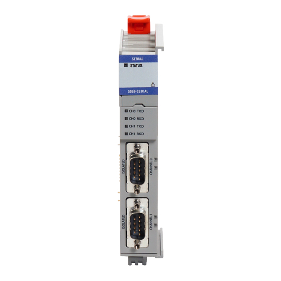
About the Compact 5000 I/O Serial Module
Details the physical components and connections of the Compact 5000 I/O Serial Module.
Chapter 2 Compact 5000 I/O Serial Module Operation in a Logix 5000 Control System
Controller and Software Compatibility for Serial Module
Lists compatible controllers and software versions for the serial module.
Local and Remote I/O Module Operation
Explains how the serial module functions as local or remote I/O within Logix 5000 systems.
I/O Module Ownership in Logix 5000 Systems
Defines the owner-controller concept for I/O modules in Logix 5000 systems.
Configuring Compact 5000 I/O Modules
Outlines the process for configuring the serial module within Logix Designer.
Chapter 3 Compact 5000 I/O Serial Module Features
Compact 5000 I/O Serial Module Features
Lists module-wide features like software configurability, RPI, fault reporting, inhibiting, and keying.
Software Configuration of the Serial Module
Details how Logix Designer is used for module configuration and information retrieval.
Fault and Status Reporting Mechanisms
Explains how fault and status data is reported via Logix Designer and status indicators.
Electronic Keying for Device Assurance
Describes electronic keying options to ensure correct device usage and prevent errors.
Chapter 4 Configure Compact 5000 I/O Serial Module
Prerequisites for Serial Module Configuration
Lists prerequisites for configuring the serial module in a Logix Designer project.
Creating a New Serial Module in Logix Designer
Provides steps for adding a serial module to a Logix Designer project using discovery or manual methods.
Editing Serial Module Configuration Parameters
Guides on modifying module configuration parameters through categories like General, Connection, and Module Info.
Chapter 5 Troubleshoot Your Module
Module Status Indicator Troubleshooting
Explains the module's status indicators and their meanings for troubleshooting.
Channel Status Indicators and Error Resolution
Details channel-specific status indicators and their recommended actions for error resolution.
Appendix A Module Tags
Module Tag Name Conventions
Outlines the naming conventions used for module tags in Logix Designer.
Tags for Generic ASCII Channel Configuration
Describes tags created when configuring channels for Generic ASCII communication.
Modbus Master Channel Tags (Input & Output)
Details input and output tags for channels configured for Modbus Master communication.
Need help?
Do you have a question about the 5069-SERIAL and is the answer not in the manual?
Questions and answers