Allen-Bradley Logix5000 User Manual
Ethernet/ip communication modules in control systems
Hide thumbs
Also See for Logix5000:
- Reference manual (708 pages) ,
- Programming manual (92 pages) ,
- Application book (56 pages)

Related Manuals for Allen-Bradley Logix5000


Summary of Contents for Allen-Bradley Logix5000
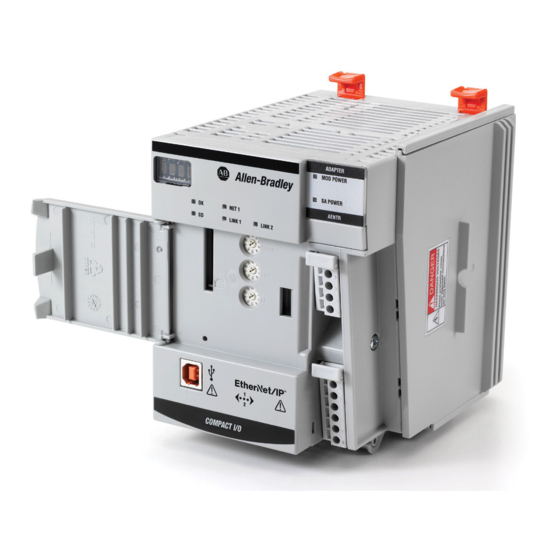
- Page 1 User Manual EtherNet/IP Communication Modules in Logix5000 Control Systems Catalog Number 5069-AEN2TR...
- Page 2 Regulatory requirements for safe work practices and for Personal Protective Equipment (PPE). Allen-Bradley, Compact I/O, CompactLogix, FactoryTalk, Kinetix, Logix5000, PanelView, PowerFlex, Rockwell Automation, Rockwell Software, RSLinx, RSLogix 5000, RSNetWorx, Studio 5000, and Studio 5000 Logix Designer are trademarks of Rockwell Automation, Inc.
-
Page 3: Table Of Contents
Table of Contents Preface Additional Resources ..........5 Chapter 1 5000 Series EtherNet/IP EtherNet/IP Communication Module Functionality . - Page 4 Table of Contents Chapter 6 Module Diagnostics 5069-AEN2TR EtherNet/IP Adapter Diagnostics with the Logix Designer Application ....... 53 Connection Category .
-
Page 5: Additional Resources
Logix5000 controllers. For example, you can use the 5069-AEN2TR EtherNet/IP adapter with ControlLogix® 5580 controllers but not with ControlLogix 5570 controllers. For more information on which Logix5000 controllers that you can use with 5000 series EtherNet/IP communication modules, see the product description at http://www.ab.com. - Page 6 Reference descriptions of the AXIS_CIP_DRIVE attributes and the Studio Network Reference Manual, publication 5000 Logix Designer® application Control Modes and Methods MOTION-RM003 Electronic Keying in Logix5000 Control Describes how to use electronic keying in Logix5000 control system Systems Application Technique, applications. publication LOGIX-AT001...
- Page 7 Chapter 5000 Series EtherNet/IP Communication Module Overview Topic Page EtherNet/IP Communication Module Functionality 5069-AEN2TR EtherNet/IP Adapter Overview EtherNet/IP networks offer a comprehensive suite of messages and services for many automation applications. These application examples use EtherNet/IP networks: • Real-time Control •...
-
Page 8: Ethernet/Ip Communication Module Functionality
• Support for full-duplex 10/100/1000 Mbps operation - Rate options are specific to modules • No network scheduling or routing table requirements • Communicate with Logix5000™ controllers to function as a remote gateway for I/O modules • Option to operate in multiple EtherNet/IP topologies •... - Page 9 5000 Series EtherNet/IP Communication Module Overview Chapter 1 Figure 1 shows how Rockwell Automation® EtherNet/IP communication modules fit into a control system. In this example, the following can occur over the EtherNet/IP network: • Controllers produce and consume tags • Controllers initiate MSG instructions that send and receive data and configure devices •...
-
Page 10: 5069-Aen2Tr Ethernet/Ip Adapter Overview
The 5069-AEN2TR EtherNet/IP adapter is the only required component of a 5069 Compact I/O™ system. The adapter performs the following functions: Adapter Overview • Facilitates high-speed data transfer between some Logix5000 controllers and remote 5069 Compact I/O modules. • Provides system-side power and field-side power to 5069 Compact I/O system. -
Page 11: Secure Digital Card
5000 Series EtherNet/IP Communication Module Overview Chapter 1 Secure Digital Card The 5069-AEN2TR EtherNet/IP adapter supports the use of a Secure Digital (SD) card to store all configuration data that is stored in non-volatile memory, for example, the adapter IP address. Remember the following: •... -
Page 12: Power A 5069 Compact I/O System
Chapter 1 5000 Series EtherNet/IP Communication Module Overview Power a 5069 Compact I/O System The 5069-AEN2TR EtherNet/IP adapter provides power to a 5069 Compact I/O system as follows: • System-side power that powers the 5069 Compact I/O system and lets modules transfer data and execute logic. -
Page 13: Mod Power
5000 Series EtherNet/IP Communication Module Overview Chapter 1 You connect external power supplies to removable terminal blocks (RTBs) to provide MOD power and SA power. We recommend that you use separate external power supplies for MOD power IMPORTANT and SA power respectively. This practice can prevent unintended consequences that can result if you use one supply. -
Page 14: Sa Power
Chapter 1 5000 Series EtherNet/IP Communication Module Overview SA Power SA power is field-side power that some 5069 Compact I/O module use to power field-side devices that are connected to them. 5069 Compact I/O System SA Power Bus When the SA power source is turned on, that is, a 5069 Compact I/O system receives field-side power, the following occurs. - Page 15 5000 Series EtherNet/IP Communication Module Overview Chapter 1 Track SA Power Bus Current Draw We recommend that you track the SA power bus current draw, max, per module, and collectively for the 5069 Compact I/O system. Consider the following with this example: •...
- Page 16 Chapter 1 5000 Series EtherNet/IP Communication Module Overview 5069-FPD Field Potential Distributor Creates Additional SA Power Buses The 5069-FPD Field Potential Distributor lets you change the field-side power distribution source for 5069 Compact I/O modules to the right of the field power distributor.
- Page 17 5000 Series EtherNet/IP Communication Module Overview Chapter 1 Create a New SA Power Bus in a 5069 Compact I/O System Figure 6 shows a 5069 Compact I/O system that uses a 5069-FPD field potential distributor to create a second SA power bus. The configuration uses separate SA power buses to isolate the digital I/O modules from the analog I/O modules.
- Page 18 Chapter 1 5000 Series EtherNet/IP Communication Module Overview SA Power - Additional Notes Remember the following: • We recommend that you use a separate power supply for the SA power connection from the power supply used with the MOD power connection. •...
- Page 19 Chapter Configure EtherNet/IP and USB Drivers on Your Workstation Topic Page Configure the Ethernet Communication Driver in RSLinx Classic Software Configure the USB Communication Driver in RSLinx Classic Software You must configure an Ethernet communication driver in RSLinx® software for your workstation to operate on the EtherNet/IP network.
-
Page 20: Configure The Ethernet Communication Driver
Chapter 2 Configure EtherNet/IP and USB Drivers on Your Workstation Configure the Ethernet Before you add an Ethernet driver, confirm that these conditions exist: Communication Driver in • Workstation is properly connected to the EtherNet/IP network. RSLinx Classic Software • IP address and other network parameters are correctly configured for the workstation. - Page 21 Configure EtherNet/IP and USB Drivers on Your Workstation Chapter 2 5. Click Browse Local Subnet. To view devices on another subnet or VLAN from the workstation running RSLinx software, click Browse Remote Subnet. 6. Select the desired driver, and click OK. 7.
-
Page 22: Rslinx Classic Software
Chapter 2 Configure EtherNet/IP and USB Drivers on Your Workstation Configure the USB To use the USB port, you must have RSLinx Classic software, version 2.51 or later, installed on your computer. The Logix Designer application version that Communication Driver in you use with your application can require a higher version of RSLinx Classic RSLinx Classic Software software. - Page 23 Configure EtherNet/IP and USB Drivers on Your Workstation Chapter 2 These RSLinx dialog boxes appear consecutively. 4. Click Finish. Rockwell Automation Publication ENET-UM004B-EN-P - November 2015...
- Page 24 Chapter 2 Configure EtherNet/IP and USB Drivers on Your Workstation 5. In RSLinx Classic software, from the Communications menu, choose RSWho. The RSLinx Workstation organizer appears, and your module appears under two different drivers, a virtual chassis and the USB port. Virtual Chassis Driver USB Port Driver Rockwell Automation Publication ENET-UM004B-EN-P - November 2015...
-
Page 25: Determine Network Parameters
Chapter Configure an EtherNet/IP Communication Module Topic Page Determine Network Parameters Set the Network IP Address on a Module Duplicate IP Address Detection Duplicate IP Address Resolution DNS Addressing ATTENTION: The EtherNet/IP communication module must be assigned a fixed network address to operate on an EtherNet/IP network. The IP address of this module must not be dynamically provided. - Page 26 Chapter 3 Configure an EtherNet/IP Communication Module If you use DNS addressing, or reference the module via host name in MSG instructions, define these parameters. Table 2 - EtherNet/IP Network Parameters for DNS Addressing EtherNet/IP Network Parameter Description Host name A host name is part of a text address that identifies the host for a module.
-
Page 27: Set The Network Ip Address On A Module
Configure an EtherNet/IP Communication Module Chapter 3 Set the Network IP Address You can use the following tools to set the network Internet Protocol (IP) address. on a Module • Rotary switches - If the network uses 192.168.1.x, we recommend using the rotary switches to set the last octet of network IP address. -
Page 28: Set The Network Ip Address With The Bootp/Dhcp Server
Chapter 3 Configure an EtherNet/IP Communication Module Figure 7 shows the process that the module uses to set the IP address. Figure 7 - How the Module IP Address is Set Module Powerup Switches set from 001…254? Is DHCP or BOOTP enabled? Module uses IP address... - Page 29 Configure an EtherNet/IP Communication Module Chapter 3 To set the IP address with BOOTP/DHCP server, complete the following steps. 1. Start the BOOTP/DHCP software. 2. From the Tools menu, choose Network Settings. 3. Type the Subnet Mask of the network. The Gateway address, Primary and/or Secondary DNS address, and Domain Name fields are optional.
- Page 30 Chapter 3 Configure an EtherNet/IP Communication Module 6. Click Add to Relation List. The New Entry dialog box appears. 7. Type an IP Address, Hostname, and Description for the module. The Hostname and Description are optional. 8. Click OK. 9. To assign this configuration to the module, wait for the module to appear in the Relation List panel and select it.
- Page 31 Configure an EtherNet/IP Communication Module Chapter 3 10. Click Disable BOOTP/DHCP. The Status field shows a success message. When power is recycled, the module uses the assigned configuration and does not issue a BOOTP request. If you do not click Disable BOOTP/DHCP, on a power cycle, the host IMPORTANT controller clears the current IP configuration and begins sending BOOTP requests again.
-
Page 32: Software Through The Usb Port
Chapter 3 Configure an EtherNet/IP Communication Module Configure the Adapter with RSLinx Classic Software through the USB Port WARNING: Do not use the USB port in hazardous locations. ATTENTION: The USB port is intended for temporary local programming purposes only and not intended for permanent connection. The USB cable is not to exceed 3.0 m (9.84 ft) and must not contain hubs. - Page 33 Configure an EtherNet/IP Communication Module Chapter 3 8. For Network Configuration Type, click Static to assign this configuration to the port. If you click Dynamic, on a power cycle, the adapter clears the current IP IMPORTANT configuration and resumes sending BOOTP requests. 9.
- Page 34 Chapter 3 Configure an EtherNet/IP Communication Module 10. Click the Advanced Port Configuration tab. Consider the following when you configure the port settings: IMPORTANT • The 5069-AEN2TR EtherNet/IP adapter supports only full-duplex mode. • The speed and duplex settings for the devices on the same Ethernet network must be the same to avoid transmission errors.
-
Page 35: Duplicate Ip Address Detection
Configure an EtherNet/IP Communication Module Chapter 3 13. In RSLinx Classic software, click RSWho. 14. Open the USB branch on the menu tree. The adapter shows the IP address. Duplicate IP Address The adapter verifies that its IP address does not match any other device IP address on the network when you perform either of these tasks: Detection •... -
Page 36: Duplicate Ip Address Resolution
Chapter 3 Configure an EtherNet/IP Communication Module Duplicate IP Address This table describes how to resolve duplicate IP addresses. Resolution Duplicate IP Address Detection Conditions Resolution Process • Both modules support duplicate IP address detection 1. The module that began operation first uses the IP address and continues to operate without interruption. 2. -
Page 37: Chapter 4
Configure an EtherNet/IP Communication Module Chapter 3 2. Configure the module parameters: • IP address • Subnet mask • Gateway address • Host name for the module • Domain name • primary/secondary DNS server addresses. In the DNS server, the host name must match the IP address of the module. - Page 38 Chapter 3 Configure an EtherNet/IP Communication Module Notes: Rockwell Automation Publication ENET-UM004B-EN-P - November 2015...
-
Page 39: Add The Module To A Project
Chapter Add an EtherNet/IP Communication Module to a Controller Project Topic Page Add the Module to a Project Time Synchronization After you install the communication module and set the IP address, you must add the module to a controller project. The project must be online to set the Speed and Duplex configurable parameters on the module. - Page 40 Chapter 4 Add an EtherNet/IP Communication Module to a Controller Project 3. On the Select Module Type dialog box, complete the following tasks: a. In the search field, type 5069-AEN2TR. b. In the Catalog Number field, select the 5069-AEN2TR, 5069 Ethernet adapter.
- Page 41 Add an EtherNet/IP Communication Module to a Controller Project Chapter 4 c. In the Module Definition area, click Change. The Module Definition dialog box appears. Rockwell Automation Publication ENET-UM004B-EN-P - November 2015...
- Page 42 Chapter 4 Add an EtherNet/IP Communication Module to a Controller Project 5. Complete the following tasks. a. Set the appropriate Revision of the firmware that is on your adapter. Major Revision (left pull-down menu) This field only displays the major revisions that are applicable to the selected series.
- Page 43 Connections from other controllers can also be broken. If an I/O connection to a device is interrupted, the result can be a loss of data. For more detailed information on Electronic Keying, see Electronic Keying in Logix5000 Control Systems Application Technique, publication LOGIX-AT001. c. Select the Connection.
- Page 44 Chapter 4 Add an EtherNet/IP Communication Module to a Controller Project 6. On the New Module dialog box, click the Connection category and complete the tasks: a. Set the Requested Packet Interval (RPI). The range is 25 750 ms, with …...
- Page 45 Add an EtherNet/IP Communication Module to a Controller Project Chapter 4 9. On the Who Active dialog box, choose the desired path and click Set Project Path. 10. Verify that the controller mode switch is in the PROG mode position 11.
- Page 46 Chapter 4 Add an EtherNet/IP Communication Module to a Controller Project 12. On the Connected To Go Online dialog box, click Download. 13. On the Download dialog box, click Download. The project downloads to the controller. The dialog box closes when the download is complete.
- Page 47 Add an EtherNet/IP Communication Module to a Controller Project Chapter 4 14. If you did not already configure the Ethernet port speed and duplex settings with RSLinx software, complete these tasks: a. Put the controller mode switch in the REM position. b.
- Page 48 Chapter 4 Add an EtherNet/IP Communication Module to a Controller Project e. On the Module Properties dialog box, click the Port Configuration category. Desired Task Action Let the module automatically set the Leave Auto-negotiate enabled. port speed and duplex settings. Manually configure your port speed and Follow these steps.
- Page 49 Add an EtherNet/IP Communication Module to a Controller Project Chapter 4 15. Click the Internet Protocol category. If needed, you can set Internet Protocol properties such as: • Domain Name • Host Name • Gateway Address • Primary and secondary DNS Server Addresses. f.
-
Page 50: Time Synchronization
Chapter 4 Add an EtherNet/IP Communication Module to a Controller Project Time Synchronization In certain situations, the I/O modules can synchronize with the adapter before the adapter synchronizes with the system Grandmaster clock. This synchronization occurrence leads to a time difference between the I/O and the Grandmaster clock until the adapter synchronizes with the Grandmaster clock. - Page 51 Chapter Use the Module on a Device-level Ring Network This chapter summarizes a DLR network. IMPORTANT For information on how to plan, configure, and monitor a DLR network, see the EtherNet/IP Embedded Switch Technology Application Guide, publication ENET-AP005. A device-level ring (DLR) network is a single-fault-tolerant ring network that is intended for the interconnection of automation devices without the need for additional switches.
- Page 52 Chapter 5 Use the Module on a Device-level Ring Network A DLR network includes the following nodes. Node Description Supervisor node A DLR network requires at least one node to be configured as ring supervisor. IMPORTANT: By default, the supervisor function is disabled on supervisor-capable devices, so they are ready to participate in a linear/star network or as a ring node on a DLR network.
-
Page 53: With The Logix Designer Application
Chapter Module Diagnostics Topic Page 5069-AEN2TR EtherNet/IP Adapter Diagnostics with the Logix Designer Application 5069-AEN2TR EtherNet/IP Adapter Diagnostics with RSLinx Software 5069-AEN2TR EtherNet/IP Adapter Diagnostic Web Pages 5069-AEN2TR EtherNet/IP Adapter Reset Button This chapter describes how to diagnose and troubleshoot issues with the 5069-AEN2TR EtherNet/IP adapter. -
Page 54: Connection Category
Chapter 6 Module Diagnostics Connection Category The Connection category displays information about the condition of the connection between the controller and the module. The data on this tab comes directly from the controller. Module Fault Module Fault displays the fault code that is returned from the controller, and text on the Module Fault that occurred. - Page 55 Module Diagnostics Chapter 6 Status The Status line at the bottom of the Module Properties dialog box displays the status that the controller has about the module. Status Meaning Standby A transient state that occurs when shutting down. Faulted The controller is unable to communicate with the module. When the status is Faulted, the Connection tab displays the fault.
-
Page 56: Module Info Category
Chapter 6 Module Diagnostics Module Info Category Module Info displays the module identity and status information about the module. See Table 3 on page 56 for parameter descriptions. You can also reset the module to its power-up state if needed. See Reset Module on page ATTENTION: When you reset a module, all connections to or through the module are closed, and can result in loss of control. - Page 57 Module Diagnostics Chapter 6 Table 3 - Module Info Parameters Parameter Description Internal State Displays the current operational state of the module: • Self-test • Flash update • Communication fault • Unconnected • Flash configuration bad • Major Fault (refer to Major/Minor Fault) •...
-
Page 58: Port Configuration Category
Chapter 6 Module Diagnostics Port Configuration Category If communication with the adapter has failed, click Refresh communication to try to restart communication with the module. Port Diagnostics On the Port Configuration category, click the Port Diagnostics button to view information for the port. See Table 4 on page 59 for parameter descriptions. - Page 59 Module Diagnostics Chapter 6 Table 4 - Port Diagnostics Parameters - Logix Designer Parameter Description Interface Counters The interface Counters values have no value when you are offline or online and there is a communication error. Octets Inbound Displays the number of octets that are received on the interface. Octets Outbound Displays the number of octets that are transmitted to the interface.
-
Page 60: Time Sync Category
Chapter 6 Module Diagnostics Time Sync Category The Time Sync displays information that is related to CIP Sync time synchronization. The information appears only if the project is online and CIP Sync is enabled. Table 5 - Time Sync Parameters Grandmaster Clock Description Displays information about the Grandmaster clock. - Page 61 Module Diagnostics Chapter 6 Table 5 - Time Sync Parameters Source Displays the time source of the Grandmaster clock. The available values are: • Atomic Clock • GPS • Radio • PTP • NTP • HAND set • Other • Oscillator Priority 1 / Priority 2 Displays the relative priority of the Grandmaster clock to other clocks in the system.
-
Page 62: 5069-Aen2Tr Ethernet/Ip Adapter Diagnostics
Chapter 6 Module Diagnostics 5069-AEN2TR EtherNet/IP You can also view diagnostic information in RSLinx® software. Diagnostic information is available on the following tabs: Adapter Diagnostics with • General Tab RSLinx Software • Port Diagnostics Tab • Connection Manager Tab • USB Tab 1. -
Page 63: Port Diagnostics Tab
Module Diagnostics Chapter 6 Port Diagnostics Tab The Port Diagnostics tab shows information for the port. See Table 6 on page 63 for parameter descriptions. Table 6 - Port Diagnostics Parameters - RSLinx Parameter Description Interface Counters Provides information relevant to receipt of packets on the interface In Octets Octets received on the interface. - Page 64 Chapter 6 Module Diagnostics Table 6 - Port Diagnostics Parameters - RSLinx Parameter Description Media Counters Provides information specific to Ethernet media you are using Alignment Errors Frames received that are not an integral number of octets in length. FCS Errors Frames received that do not pass the FCS (Frame Check Sequence) check.
-
Page 65: Connection Manager Tab
Module Diagnostics Chapter 6 Connection Manager Tab Table 7 for a description of the Connection Manager properties. Table 7 - Connection Manager Properties Field Description Requests Number of open/close connection requests that this module has received. Format Rejects Number of open/close connection requests that this module has rejected because the request was not formatted correctly or because some parameter value was not within a supported range of values. -
Page 66: Usb Tab
Chapter 6 Module Diagnostics USB Tab The USB tab provides the following information about the adapter USB object. Table 8 - General Information Attribute Name Description State State (Initializing, Fault, Initialized, Configured, Ready, and Reserved) of the USB interface. Suspend The USB interface was suspended by the host. -
Page 67: 5069-Aen2Tr Ethernet/Ip Adapter Diagnostic Web
Module Diagnostics Chapter 6 Table 10 - Media Counters provide diagnostic information in the USB driver layer. Counter Name Description Rx Byte Counter Total number of bytes received. Rx Dropped Counter Total number of received bytes dropped. Tx Byte Counter Total number of bytes sent. -
Page 68: Access Web Browser Support
Chapter 6 Module Diagnostics Access Web Browser Support To access the diagnostic web pages, follow these steps. 1. Open your web browser. 2. In the Address field, type the IP address of the adapter and press Enter. The Home diagnostic web page appears. EtherNet/IP Module Internet Protocol (IP) Address 3. -
Page 69: Diagnostic Overview Page
Module Diagnostics Chapter 6 Diagnostic Overview Page The Diagnostic Overview web page shows the status of the adapter. Rockwell Automation Publication ENET-UM004B-EN-P - November 2015... -
Page 70: Network Settings
Chapter 6 Module Diagnostics Network Settings The Network Settings diagnostic web page shows the settings for the Network Interface configuration, Ethernet Interface Configuration, and the Ethernet ports. Rockwell Automation Publication ENET-UM004B-EN-P - November 2015... -
Page 71: Ethernet Statistics
Module Diagnostics Chapter 6 Ethernet Statistics The Ethernet Statistics diagnostic web page shows the status of communication activity on the Ethernet network. The most commonly monitored fields are described in Table Table 11 - Ethernet Statistic Fields Field Specifies Ethernet Port 1 and Ethernet Port 2 Interface State Whether the port is turned off or on. -
Page 72: Ring Statistics
Chapter 6 Module Diagnostics Table 11 - Ethernet Statistic Fields Field Specifies Media Counters Port 1 and Port 2 Alignment Errors A frame containing bits that do not total an integral multiple of eight. FCS Errors A frame containing eight bits, at least one of which has been corrupted. Single Collisions The number of outgoing packets that encountered only one collision during transmission. -
Page 73: 5069-Aen2Tr Ethernet/Ip Adapter Reset Button
Module Diagnostics Chapter 6 5069-AEN2TR EtherNet/IP You can reset the adapter to its factory default values with the reset button. Adapter Reset Button ATTENTION: When you reset a module, all connections to or through the module are closed, and can result in loss of control. WARNING: When you press the reset button while power is on, an electrical arc can occur. - Page 74 Chapter 6 Module Diagnostics Notes: Rockwell Automation Publication ENET-UM004B-EN-P - November 2015...
-
Page 75: 5069-Aen2Tr Ethernet/Ip Adapter Status Indicators
Appendix EtherNet/IP Communication Module Status Indicators EtherNet/IP communication modules have multi-character displays and status indicators to assist with module performance and diagnostics. 5069-AEN2TR EtherNet/IP You can view the status with the following: • Multi-character Display Adapter Status Indicators • Status Indicators Multi-character Display The 4-character display shows the following information. -
Page 76: Status Indicators
Appendix A EtherNet/IP Communication Module Status Indicators Status Indicators The 5069-AEN2TR EtherNet/IP adapter has these status indicators. Indicator State Description There is no power applied to the device. Steady green The device is operating in a normal condition. Flashing red •... -
Page 77: Rockwell Automation Publication Enet-Um004B-En-P - November
Appendix Module Tags Module tags are created when you add an EtherNet/IP communication module to the Logix Designer application project, and set the connection to Status. Table 13 - 5069-AEN2TR EtherNet/IP Adapter Module Tags Tag Name Data Type Definition Valid Values RunMode BOOL Module’s operating state... -
Page 78: Appendix B
Appendix B Module Tags Table 13 - 5069-AEN2TR EtherNet/IP Adapter Module Tags Tag Name Data Type Definition Valid Values Port2FullDuplex BOOL Indicates if the numbered Ethernet port, if it is connected, is running full-duplex mode or • 0 = Ethernet port is running in half- half-duplex mode. -
Page 79: Appendix B
Module Tags Appendix B Table 13 - 5069-AEN2TR EtherNet/IP Adapter Module Tags Tag Name Data Type Definition Valid Values HMIPacketRate DINT The number of Class 3 packets and unconnected packets that are sent and received by the device in the previous second. IOPacketRate DINT The number of class 0 and class 1 packets transmitted or received by the adapter in the... -
Page 80: Appendix B
Appendix B Module Tags Notes: Rockwell Automation Publication ENET-UM004B-EN-P - November 2015... - Page 81 Index Numerics DNS addressing 36 domain name 26 4-character display duplicate address detection 35 5069-AEN2TR adapter 75 5069-AEN2TR adapter configure set network IP address 27 Ethernet communication driver 20 diagnostics web pages 68 Ethernet statistics 71 with Logix Designer 53 EtherNet/IP communication driver 20 with RSLinx software 62 EtherNet/IP communication module...
- Page 82 Index Refresh 57 reset button 5069-AEN2TR adapter 73 ring statistics 72 rotary switches set IP network address 27 RSLinx software 5069-AEN2TR adapter diagnostics 62 configuring network parameters 32 Ethernet communication driver 20 setting network IP address 27 USB communication driver 22 set network IP address 27 BOOTP/DHCP server 27 rotary switches 27...
- Page 84 Rockwell Automation Support Rockwell Automation provides technical information on the Web to assist you in using its products. http://www.rockwellautomation.com/support you can find technical and application notes, sample code, and links to software service packs. You can also visit our Support Center at https://rockwellautomation.custhelp.com/ for software updates, support chats and forums, technical information, FAQs, and to sign up for product notification updates.
Need help?
Do you have a question about the Logix5000 and is the answer not in the manual?
Questions and answers