Table of Contents
Advertisement
Advertisement
Table of Contents

Related Manuals for Mark-10 BG500


Summary of Contents for Mark-10 BG500
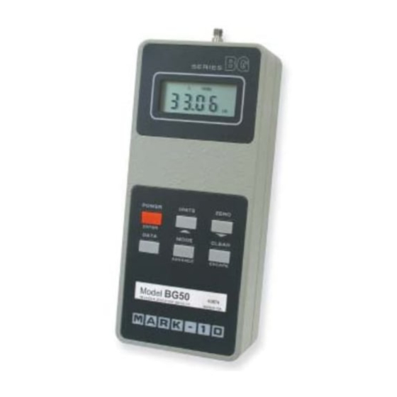
- Page 1 Series DIGITAL FORCE GAUGES User's Guide...
-
Page 2: Table Of Contents
User's Guide TABLE OF CONTENTS GENERAL - SECTION 1 ..............2 Controls ................2 Orientation ................2 Mounting ................3 POWER - SECTION 2 ................ 3 CONFIGURATION - SECTION 3 ............3 FILTERS - SECTION 4 ............... 6 EXTERNAL TRIGGER MODE - SECTION 5 ........6 SET POINTS - SECTION 6 .............. -
Page 3: General - Section 1
Series BG GENERAL Section 1 Controls Six keys on the front panel are used for all functions and control of the instrument. Some have more than one function, depending on the mode of operation. The main functions are labeled above the keys and the secondary functions are below the keys in smaller type. -
Page 4: Mounting
User's Guide Mounting SERIES BOTTOM PLATE DOWEL PIN 0.125 [3.2] MOUNTING PLATE Ø 0.187 [4.75] Gauge shown mounted on Model TSC test stand Recommended use of a dowel pin POWER Section 2 gauge is powered by a 7.2-volt NiCd rechargeable battery. Since batteries are subject to self-discharge, it may be necessary to recharge the unit after a prolonged period of storage. - Page 5 Series BG The software version number will be displayed for a short time followed by "FLtA". The following secondary functions of keys are used during the configuration process. ADVANCE Step through menu choices ENTER Select a menu choice ESCAPE Quit any function (no change) &...
- Page 6 User's Guide bcd d Mitutoyo BCD output disabled bcd E Mitutoyo BCD output enabled nPOL Mitutoyo readings without polarity (absolute value) Mitutoyo readings with polarity; positive for compres- sion, negative for tension Et d External trigger disabled Et E External trigger enabled in edge mode Et L External trigger enabled in level mode EtHL...
-
Page 7: Filters - Section 4
Series BG CAL - Calibration. See Section 10. FILTERS Section 4 For maximum flexibility in noise suppression and peak capturing ability of the instru- ment, there are two types of filters available to the user: analog and digital. The analog filter is a simple RC network with a cutoff frequency of 2.5 Hz and attenu- ation of 20 dB/decade. -
Page 8: Set Points - Section 6
User's Guide SET POINTS Section 6 This feature is useful for tolerance checking (GO/NO GO) or alarm indication in process control applications. Two limits, high and low, are specified and stored in the non- volatile memory of the instrument and all readings are compared to these limits. The results of the comparisons are indicated through the three open-collector outputs pro- 40 ma MAX... -
Page 9: Gauge Control Language - Section 8
Series BG Section 8 GAUGE CONTROL LANGUAGE The instrument can be controlled by an external device through the RS-232 channel. The following is a list of supported commands and their interpretations. All commands must be terminated with a Carriage Return character (hex 0D) or with a Carriage Return/Line Feed combination (hex 0D+0A). - Page 10 User's Guide FULL RS-232 transmission with units RS-232 transmission without units (only numeric values) Enable Mitutoyo output MITD Disable Mitutoyo output Mitutoyo outputs with polarity. (+ for compression, - for tension) NPOL Mitutoyo outputs without polarity (absolute value) Print/send data to a Mitutoyo compatible device Set output bit (open collector, pull to ground).
-
Page 11: Outputs - Section 9
Series BG OUTPUTS Section 9 RS-232 The data transmission can be initiated by pressing the DATA key or by an external device by sending ASCII "?" to the gauge. The gauge will respond by sending the current reading in either full or numeric format, depending on the configuration settings (see Section 3). -
Page 12: Calibration - Section 10
7.2 NiCd battery or included AC adapter/charger Battery life: 8-10 hours per charge Weight: 0.9 lbs [0.4 kg] Capacity x graduation BG012 0.12 x 0.00005 lbF 50 x 0.02 gF 0.5 x 0.0002 N BG025 0.25 x 0.0001 lbF 100 x 0.05 gF 1 x 0.0005 N... -
Page 13: Dimensions
WARRANTY Section 12 Mark-10 Corporation expressly warrants to its buyer for three (3) years from the date of delivery that the goods sold are free from defects in workmanship and materials. Mark-10 Corporation will, at its option, repair or replace or refund the purchased price of goods found to be defective.
Need help?
Do you have a question about the BG500 and is the answer not in the manual?
Questions and answers