
Related Manuals for TECO L510-201-H1F-P


Summarization of Contents
Preface
0.1 Preface
To extend the performance of the product and ensure personnel safety, please read this manual thoroughly before using the inverter.
Safety Precautions
1.1 Before Power Up
Make sure the main circuit connections are correct and line voltage complies with inverter specifications.
1.2 During Power Up
Details regarding momentary power loss and automatic restart based on parameter settings.
1.3 Before Operation
Ensure model/inverter capacity match parameter settings and note voltage display.
1.4 During Operation
Safety measures for operation, including avoiding touching components and environmental limits.
Part Number Definition
2.1 Model part number
Explains the structure and components of the L510 model part number.
2.2 Standard Product Specification
Details product specifications including voltage, frequency, HP, KW, and filter options.
Environment & Installation
3.1 Environment
Specifies installation environment conditions: protection class, operating/storage temp, humidity, shock.
3.2 Installation
Describes mounting on a flat surface and DIN rail installation methods.
3.3 Wiring Guidelines
Connects supply power and motor cables to terminals, with warnings and voltage/current ratings.
3.4 Specifications
Lists detailed specifications for 100V, 200V single/three phase, and 400V models.
Standard Wiring
3.5.1 Single phase (NPN input)
Provides wiring diagram for single phase NPN input configurations.
3.5.2 Single phase (PNP input)
Illustrates wiring diagrams for single phase PNP input configurations.
3.5.3 Three phase (NPN input)
Shows wiring diagrams for three phase NPN input configurations.
3.5.4 Three phase (PNP input)
Details wiring diagrams for three phase PNP input configurations.
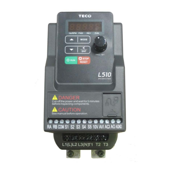
Terminal Description
3.6.1 Description of main circuit terminals
Explains the function of main circuit terminals for single and three phase connections.
3.6.2 Control circuit terminal description
Describes control circuit terminals, including NPN and PNP configurations.
Outline Dimensions
3.7 Outline Dimensions (Frame 1)
Provides outline dimensions and weight for Frame 1 models.
3.7 Outline Dimensions (Frame 2)
Details outline dimensions and weight for Frame 2 models.
EMC Filter Disconnection
3.8 EMC Filter Disconnection
Instructions for disconnecting the built-in EMC filter and related notes.
Software Index
4.1 Keypad Description
Explains functions of digital displays, LEDs, variable resistor, and keys on the operator panel.
4.1.2 Digital display Description
Details the alpha-numerical display format and indication formats.
4.1.3 Digital display set up
Describes how to set up the digital display screens on power up and user selectable formats.
4.1.4 Example of keypad operation
Shows examples of modifying parameters and frequency using the keypad.
Programmable Parameter Groups
Group 00- Basic parameters group
Details basic parameters like motor rotation, run source, and frequency settings.
Group 01- V/F Pattern selection & Setup
Covers V/F pattern selections, max frequency, and voltage ratios.
Group 02- Motor parameters
Details motor parameters like no load current, rated current, and rated speed.
Group 03- Multi function Digital Inputs/Outputs
Explains multifunction input terminals (S1-S5) and output relay (RY1) functions.
Parameter Function Description
00- Basic parameter group
Explains basic parameters like motor direction control and run command source selection.
01- V/F command group
Explains V/F patterns, max voltage, and frequency ratios for 50Hz and 60Hz.
03- External digital inputs & Realy Output functions
Explains multifunction input terminal settings for forward/stop commands.
04- External analog signal input / output functions
Covers analog voltage & current input selections and scaling formulas.
Troubleshooting and Maintenance
5.1 Error display and corrective action
Lists errors not manually recoverable and those recoverable manually/automatically.
5.1.2 Keypad Operation Error Instruction
Explains keypad operation error codes like LoC, Err1, Err2, and Err5.
5.2 General troubleshooting
Provides troubleshooting steps for common issues like motor direction, speed regulation, and no run.
5.3.1 Quick troubleshooting of the Inverter
Flowchart for initial troubleshooting of inverter faults and issues.
Routine and periodic inspection
5.4 Routine and periodic inspection
Checklist for routine and periodic inspection of inverter, terminals, wiring, and components.
5.5 Maintenance
Lists essential checks for ensuring inverter reliability and safety.
Peripherals Components
6.1 Reactor Specifications
Lists specifications for reactors used with the L510 series inverters.
6.3 Fuse Specification
Provides fuse specifications (HP, KW, Rating) for L510 models.
6.5 Barking Resistor
Details specifications for braking resistors, including power, voltage, and ED%.
L510 parameters setting list
Appendix I L510 parameters setting list
Provides a comprehensive list of parameter codes and suggested settings.
Need help?
Do you have a question about the L510-201-H1F-P and is the answer not in the manual?
Questions and answers