Table of Contents
Advertisement
INSTALLATION AND
OPERATION MANUAL
Heat Pump
Pool & Spa
Heater
Model Series
2450, 3450, 4450,
5450, 6450,
6450PD, 6450HC,
8450 & 8450HC
FOR YOUR SAFETY: Do not store or use gasoline or other flammable vapors and
liquids or other combustible materials in the vicinity of this or any other appliance.
To do so may result in an explosion or fire.
NOTE: The instructions in this manual are for the use of qualified individuals specially trained and experienced
in the installation and maintenance of this type of equipment and related system components. Installation and
service personnel are required by some states to be licensed. Persons not qualified shall not attempt to install,
service, or maintain this equipment.
This manual should be maintained in legible condition and kept adjacent to the heat pump pool heater or in a
safe place for future use.
Catalog No. 6000.56C
Effective: 01-12-18
Replaces: 11-20-17
92-105917-01-04
Advertisement
Table of Contents

Related Manuals for Raypak 5450 Series


Summarization of Contents
Installation and Safety Overview
Model Series Identification
Identifies the heat pump pool and spa heater model series covered in the manual.
Critical Safety Warnings
Provides essential safety precautions regarding flammable materials and operation by qualified personnel.
Requirement for Qualified Personnel
Emphasizes that only trained and qualified individuals should install or service the equipment.
Warranty Registration and Unit Information
Warranty Registration Process
Encourages users to register their unit quickly for warranty assurance.
Locating Model and Serial Numbers
Guides users to find the unit's model and serial number for registration and service.
Water Chemistry Management
Recommended Water Chemistry Levels
Details ideal water chemistry parameters for fiberglass pools, spas, and other types.
Chemical Treatment Guidelines
Advises on chemical dosing, chlorinators, and shock treatments to protect the heater.
Hazard Alerts and Safety Guidelines
Hazard Alert Definitions
Explains the meaning of DANGER, WARNING, CAUTION, and NOTE labels.
Health Risks from Water Temperature
Outlines safety guidelines for spa and hot tub water temperatures, including risks for children and pregnant women.
Chemical and Refrigerant Safety
Warns about improper chemical content damaging the heater and the use of R-410A refrigerant.
Unit Introduction and Installation Site
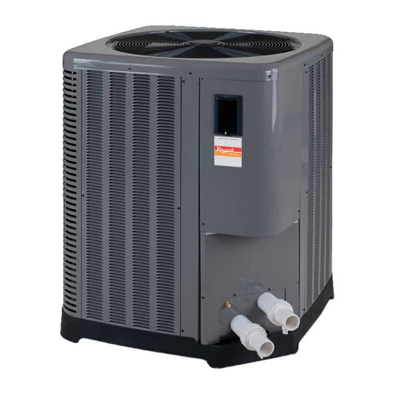
Heat Pump Pool Heater Overview
Introduces the unit's efficiency, operation, and comparison to other heater types.
Installation Site Requirements
Details essential site preparation, including clearances, base requirements, and outdoor installation.
Airflow and Water Management
Covers proper air discharge clearance and water piping considerations for optimal performance.
Installation Clearances and Handling Details
Fig. 1: Installation Clearances Diagram
Illustrates required minimum clearances around the heat pump pool heater for proper operation.
Fig. 2: Base Design and Handling
Shows the unit's base design for handling and explains proper lifting methods.
Site Preparation and Environmental Factors
Covers keeping the area clear, freeze protection, and managing rain run-off.
Hurricane Tie-Down Instructions (Model 2450)
Fig. 3: Hurricane Tie-Down Instructions
Provides detailed diagrams for securing the Model 2450 unit against high winds.
Tie-Down Clip Layout and Offsets
Specifies dimensions and placement for tie-down clips on the unit base.
Anchor Schedule for Concrete Installation
Details the required anchor type, size, and spacing for concrete installation.
Hurricane Tie-Down Instructions (Models 3450-4450)
Fig. 4: Hurricane Tie-Down Instructions
Illustrates tie-down procedures for Models 3450 and 4450.
Tie-Down Clip Layout and Offsets
Specifies dimensions and placement for tie-down clips on the unit base.
Anchor Schedule for Concrete Installation
Details the required anchor type, size, and spacing for concrete installation.
Hurricane Tie-Down Instructions (Models 5450-8450)
Fig. 5: Hurricane Tie-Down Instructions
Provides diagrams for securing Models 5450, 6450, and 8450 against high winds.
Tie-Down Clip Layout and Offsets
Specifies dimensions and placement for tie-down clips on the unit base.
Anchor Schedule for Concrete Installation
Details the required anchor type, size, and spacing for concrete installation.
Electrical and Water Connection Requirements
Table A: Electrical Power Requirements
Lists typical system electrical power requirements, including breaker size and wire length recommendations.
Electrical Connection Standards
Covers wiring compliance, flexible conduit, disconnect means, and relevant electrical codes.
Water Connection Procedures
Details correct inlet/outlet connections, chemical feeder installation, and pipe sizing.
System Plumbing and Control Interface
Water Connections and Valve Requirements
Explains plumbing connections, necessary shut-off/diverter valves, and drain plugs for winterizing.
Table B: Pressure Drop Data
Provides pressure drop values across the heat pump pool heater for various flow rates.
HPPH Control Display Overview
Describes the function and operation of the HPPH digital control display and buttons.
Control Display and User Mode Operations
Fig. 7: HPPH Control Display
Illustrates the HPPH control display interface and button functions.
User Mode Selections and Operation
Details how to select and operate the unit in different user modes like Pool Heat, Spa, and Timed Spa.
Temperature Setpoint Adjustment
Explains how to increase or decrease desired water temperatures for Pool and Spa modes.
Advanced Control Modes and Menus
HEAT/COOL Model Modes
Describes specific modes for HEAT/COOL models, including Pool Auto and TIMED SPA.
Remote Mode Operation
Explains how to access and use the Remote Mode for external control.
Installer/Service Menu Access
Guides users on how to access the Installer/Service menu for advanced settings.
User Menu: Basic Control Settings
Table C: USER MENU Configuration
Lists user-adjustable settings including time, temperature units, max temps, and pump periods.
Time and Temperature Unit Settings
Covers setting the current time and choosing between Celsius or Fahrenheit display.
Pool and Spa Maximum Temperature Limits
Defines the maximum adjustable temperatures for Spa and Pool modes.
User Menu: Pump Period and Valve Configuration
Pump Period Scheduling and Speed Control
Details setting pump ON/OFF times, pump speeds, and pump periods.
3-Way Valve Configuration for Pump Periods
Explains how to set the positions of 3-way valves for each scheduled pump period.
Installer/Service Menu: HEAT ONLY Configuration
Table D: HEAT ONLY Installer Settings
Details installer-configurable settings for HEAT ONLY models, including time and pump periods.
Installer Time and Pump Scheduling
Covers setting the current time and configuring pump periods for HEAT ONLY units.
Installer 3-Way Valve Settings
Explains how installers configure 3-way valve positions for HEAT ONLY models.
Installer/Service Menu: Faults and Operational Data
Installer Pump and Valve Settings (cont.)
Continues installer settings for pump periods, speeds, and valve positions.
Fault History and Clearing Procedures
Describes how to view, interpret, and clear fault history logs.
Run Hours and Cycles Monitoring
Explains how to access and interpret the unit's run hours and compressor cycles.
Installer/Service Menu: Sensor and System Settings
Sensor and Voltage Data Readings
Guides on viewing sensor temperatures and system voltage for diagnostics.
Installer Menu and Pump Operation Control
Covers installer access to pump operation settings and pump heat control.
Valve Operation and Auxiliary Mode Configuration
Details settings for controlling 3-way valves and configuring auxiliary output modes.
Installer/Service Menu: Defrost and System Parameters
Defrost Temperature and Lockout Settings
Covers configuring defrost parameters and outside temperature lockout.
Model Type and EXV Configuration
Explains how to set the unit model type and configure EXV settings.
Factory Defaults and Brownout Protection
Details resetting factory defaults and enabling brownout detection.
Installer/Service Menu: POWER DEFROST Configuration
Table E: POWER DEFROST Installer Settings
Lists installer-configurable settings for POWER DEFROST models, including time and pump periods.
Installer Time and Pump Scheduling (PD)
Covers setting current time and configuring pump periods for POWER DEFROST units.
Installer 3-Way Valve Settings (PD)
Explains how installers configure 3-way valve positions for POWER DEFROST models.
Installer/Service Menu: Faults and Operational Data (PD)
Installer Pump and Valve Settings (PD Cont.)
Continues installer settings for pump periods, speeds, and valve positions for PD models.
Fault History and Clearing Procedures (PD)
Describes how to view, interpret, and clear fault history logs for PD models.
Run Hours and Cycles Monitoring (PD)
Explains how to access and interpret PD unit's run hours and compressor cycles.
Installer/Service Menu: HEAT/COOL Sensor and Operation Settings
Sensor and Voltage Data Readings (HC)
Guides on viewing sensor temperatures and system voltage for HEAT/COOL diagnostics.
Installer Menu and Pump Control (HC)
Covers installer access to pump operation settings and pump heat control for HC models.
Valve Operation and Auxiliary Mode (HC)
Details settings for controlling 3-way valves and configuring auxiliary output modes for HC models.
Installer/Service Menu: HEAT/COOL System Parameters
Auxiliary Outputs and Cooling Deadband (HC)
Covers settings for auxiliary outputs and cooling deadband for HEAT/COOL models.
Defrost, Lockout, and Model Type (HC)
Details settings for defrost, lockout, and model type for HEAT/COOL models.
EXV, Brownout, and Factory Defaults (HC)
Details settings for EXV, brownout detection, and factory defaults for HEAT/COOL models.
Installer/Service Menu: HEAT/COOL Pump Scheduling
Table F: HEAT/COOL Installer Settings
Lists installer-configurable settings for HEAT/COOL models, including time and pump periods.
Remote Pool and Time Settings (HC)
Covers settings for remote pool control and current time for HEAT/COOL models.
Installer Pump Period Configuration (HC)
Details how installers configure pump periods, speeds, and valve positions for HEAT/COOL models.
Installer/Service Menu: Faults and Operational Data (HC)
Installer Pump and Valve Settings (HC Cont.)
Continues installer settings for pump periods, speeds, and valve positions for HEAT/COOL models.
Fault History and Clearing Procedures (HC)
Describes how to view, interpret, and clear fault history logs for HEAT/COOL models.
Run Hours and Cycles Monitoring (HC)
Explains how to access and interpret HEAT/COOL unit's run hours and compressor cycles.
Installer/Service Menu: Sensor and Operation Settings (HC)
Sensor and Voltage Data Readings (HC Cont.)
Provides further details on viewing sensor temperatures and system voltage for HC diagnostics.
Installer Menu and Pump Control (HC Cont.)
Covers additional installer settings for pump operation and pump heat control for HC models.
Valve Operation and Auxiliary Mode (HC Cont.)
Details further settings for controlling 3-way valves and configuring auxiliary output modes for HC models.
Installer/Service Menu: System Parameters (HC)
Auxiliary Outputs and Cooling Deadband (HC Cont.)
Covers additional settings for auxiliary outputs and cooling deadband for HEAT/COOL models.
Defrost, Lockout, and Model Type (HC Cont.)
Details additional settings for defrost, lockout, and model type for HEAT/COOL models.
EXV, Brownout, and Factory Defaults (HC Cont.)
Details additional settings for EXV, brownout detection, and factory defaults for HEAT/COOL models.
Control Operations and User Interface
User Menu Access and Settings
Explains how to access and modify user settings like time, temperature units, and max temperatures.
Pump Control and Scheduling Features
Details the unit's pump control capabilities, including scheduling and variable speed options.
Lockout Features and Control Security
Describes Low Ambient Lockout and Control Lock Box Mode for unit protection and security.
Auxiliary Output Mode Functions
AUX Mode Configuration Options
Outlines the four selectable modes for auxiliary output control: OFF, AUX OUTPUT, REMOTE OUT, EXT HEAT.
REMOTE OUT Mode Operation
Explains how to use REMOTE OUT for controlling other heaters or multiple HPPH units.
EXT HEAT Mode Usage
Describes using EXT HEAT mode to integrate solar systems or other primary heat sources.
Operating Modes and System Monitoring
Pool and Spa Operating Modes
Details Pool Heat, Pool Cool, Pool Auto, and TIMED SPA modes for temperature control.
Remote Pool Operation and Warnings
Covers remote pool operation and important warnings related to its use.
Fault History and Run Hour Tracking
Explains how to access and interpret fault history and unit run hours/cycles.
Compressor Protection and Defrost Logic
Compressor Start Delay and Minimum Run Time
Describes protections to prevent compressor short-cycling and ensure minimum run times.
Defrost Operation Logic
Explains the defrost cycle initiation and termination for HEAT ONLY, POWER DEFROST, and HEAT/COOL models.
3-Way Valve Control Mechanisms
Details how the control system manages 3-way valves for pool/spa selection and pump scheduling.
System Operation and Control Logic
Water Pressure Switch Functionality
Explains the role of the water pressure switch in unit operation and valve control.
Initial Unit Power-Up Sequence
Outlines the steps the control system performs upon initial power application.
System Configuration and Setup Parameters
Lists essential parameters that need to be programmed during initial installation.
Digital Control Features and Heat/Cool Operation
Selecting Operating Modes
Guides users on selecting different operating modes for the unit.
Adjusting Water Temperature Setpoints
Explains how to change the desired pool or spa water temperatures.
Heat/Cool Operation Characteristics
Describes how heating and cooling modes function, including efficiency considerations.
System Start-Up, Maintenance, and Storage
System Start-Up Procedures
Step-by-step guide for initiating the unit's operation after installation.
Seasonal Start-Up and Annual Checks
Procedures for preparing the unit for the heating season and performing annual maintenance.
Summer Shutdown and Freeze Protection
Instructions for properly securing the unit for summer or protecting it from freezing.
Maintenance and Troubleshooting Introduction
Continuous Pump Operation for Freeze Prevention
Discusses using continuous pump operation as a method for freeze damage prevention.
Routine Maintenance and Cleaning
Covers cleaning the air coil, cabinet care, and checking condensation drain holes.
Troubleshooting Common Issues
Introduces the troubleshooting section, highlighting the use of fault messages.
Troubleshooting Unit Performance
Diagnosing Unit Not Running Problems
Provides steps to troubleshoot when the unit fails to start or run.
Addressing Excessive Condensation Issues
Guides on identifying and resolving issues related to excessive condensation or suspected leaks.
Troubleshooting Checks and Status Indicators
General Troubleshooting Pre-Checks
Lists essential checks to perform before contacting service, ensuring basic connections and settings are correct.
Operational Status Message Guide
Explains the meaning of various operational status messages displayed by the control panel.
Error Message Reference and Troubleshooting
Table H: Error Messages and Descriptions
Lists all possible error messages, their descriptions, and potential causes.
Troubleshooting Specific Error Codes
Provides recommended troubleshooting steps for each identified error message.
Service Procedures and Verification
Service Call Verification Process
Outlines steps to verify unit operation and gather necessary information before requesting service.
Accessing Internal Components
Details how to safely remove the control panel cover to access internal components for service.
Internal Component Access and Reassembly
Removing the Junction Box Assembly
Provides step-by-step instructions for removing the junction box assembly for wiring access.
Reassembling Unit Panels and Covers
Guides on properly reinstalling the junction box, control panel, and other covers after servicing.
Plumbing Schematic - No External Bypass
Fig. 12: Plumbing Schematic - No External Bypass
Illustrates the plumbing configuration for systems without an external bypass, suitable for lower pump capacities.
Pump Size Guidelines for Plumbing
Notes on pump flow rates that do not require an external bypass.
Plumbing Schematic - External Bypass Required
Fig. 13: Plumbing Schematic - External Bypass
Illustrates the plumbing configuration requiring an external bypass for higher pump capacities.
External Bypass Valve Adjustment
Advises on adjusting the bypass valve to ensure minimum flow through the heater.
Pool Piping Configuration and Recommendations
Fig. 14: Pool Piping Diagram
Shows a general schematic for piping the heat pump pool heater and gas pool heater.
Piping Notes and Recommendations
Provides essential notes on pipe sizing, valve placement, and system design considerations.
Multiple Unit Pool Piping Diagrams
Fig. 15: Multiple Unit Piping Schematic
Illustrates piping configurations for multiple heat pump pool heater installations.
Minimum Pipe Size Chart
Provides a chart detailing minimum pipe sizes based on the number of units and flow rates.
Wiring Diagram and Component Legend
Wiring Diagram - 208V/230V Single-Phase
Presents the electrical wiring diagram for single-phase digital control models.
Wiring Diagram Legend and Information
Explains the symbols used in the wiring diagram and provides important wiring information.
Remote Control and Automation Integration
Installing Remote Control Devices
Guides on connecting external automation controllers to the heat pump pool heater.
2-Wire Controller Setup (Heat Only)
Details wiring and configuration for 2-wire controllers in Heat Only mode.
3-Wire and Chill Mode Controller Setup
Explains wiring and configuration for 3-wire controllers and "Chill" mode for HEAT/COOL models.
Sensor Resistance Values and Diagnostics
Table I: Sensor Resistance Values
Provides tables of resistance values for 10K and 100K sensors at various temperatures.
Sensor Operation and Error Interpretation
Explains how sensors function and how to interpret related error messages.
Need help?
Do you have a question about the 5450 Series and is the answer not in the manual?
Questions and answers