
Related Manuals for SBM SB-1050


Summarization of Contents
Important Safety Information
Machine Stability and Power Supply
Ensure stable placement and correct power supply for safe operation.
Grounding, Overload, and Cleaning Safety
Proper grounding, avoiding overloads, and safe cleaning procedures.
Operational Precautions
Rules on object insertion, water, cords, pets, supplies, and accessibility.
Service and Interlock Safety
Do not remove covers or defeat interlocks; refer servicing to professionals.
Battery Replacement Safety
Caution on battery type replacement to prevent explosion risk.
Safety Notes
Hazardous Moving Parts Warning
Warning about hazardous moving parts and keeping body parts away.
Battery Handling Caution
Warning about battery replacement type and disposal.
1 Installation
1-1. Unpacking List
Lists all items included with the machine, including optional items.
1-2. Choosing a Location
Guidelines for selecting an appropriate and safe place for the machine.
1-3. Handling the Machine
Instructions on the correct method for lifting and moving the machine safely.
1-4. Setting Up Your Machine
1-4-1. Power Cord
How to connect the power cord to the machine and power outlet.
1-4-2. Printer
Instructions for connecting a printer to the machine's serial interface port.
2 Description of the Parts
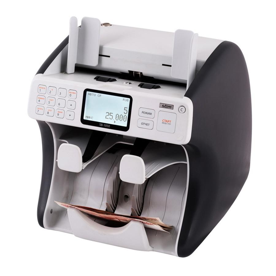
2-1. Out Side
Identifies and labels the external components of the machine.
2-2. Interface Port
Details the different types of interface ports and their functions.
3 Overview of Control Panel
3-1. Operation Panel
Shows a diagram of the control panel with labeled buttons.
3-2. Key Define
Explains the function of each key on the operation panel.
4 Reject Reason and Error Message
4-1. Reject Reason
Explains different reject reasons displayed by the machine.
5 Board & Component
5-1. Connection Diagram
Illustrates the internal wiring and component connections.
5-2. Board Descriptions
5-2-1. P-MAIN
Details the components and layout of the P-MAIN board.
5-2-2. P-POWER_IO
Details the components and layout of the P-POWER_IO board.
5-2-3. P-AMP
Details the components and layout of the P-AMP board.
5-2-4. P-IR_RCV
Details the components and layout of the P-IR_RCV board.
5-2-5. P-MRS_L
Details the components and layout of the P-MRS_L board.
5-2-6. P-MRS_R
Details the components and layout of the P-MRS_R board.
5-2-7. P-MRA
Details the components and layout of the P-MRA board.
5-2-8. P-JP_TRN
Details the components and layout of the P-JP_TRN board.
5-2-9. P-SP_TRN
Details the components and layout of the P-SP_TRN board.
5-2-10. P-JPSP_RCV
Details the components and layout of the P-JPSP_RCV board.
5-2-11. P-IF
Details the components and layout of the P-IF board.
5-2-12. P-OPE
Details the components and layout of the P-OPE board.
7 SERVICE MENU 1
7-1. How to enter SERVICE MENU 1
Step-by-step guide to access the Service Menu 1.
7-2. Service Menu1
Lists the main options available within Service Menu 1.
Service Menu 1 Options
1. ERROR STOP CTRL.
Controls whether the machine stops on errors or continues operation.
2. SENSOR LEVEL
Adjusts reference levels for Hopper and Double detection sensors.
3. SYSTEM REPORT
Displays counting reports and software/currency version information.
4. SET A/S CALL No.
Allows setting the machine's After-Sales service telephone number.
5. SET MACHINE S/N
For displaying and setting the machine's serial number.
6. SHADING
Explains the purpose of shading and its sub-options.
7. SENSOR SELECT
Allows enabling or disabling specific sensors for testing or operation.
8 SERVICE MENU 2
8-1. How to enter SERVICE MENU 2
Instructions to access the Service Menu 2.
8-2. Service Menu2
Lists the available test categories in Service Menu 2.
Service Menu 2 Tests
1. SENSOR TEST
Performs tests on various sensors including LED, Hopper, and logic status.
IR LOGIC TEST
Tests for IR sensor channels.
IRA TEST
Tests for IR note patterns.
2. KEY TEST
Verifies the functionality of each key on the control panel.
3. MOTOR TEST
Tests the driving and feeding functions of the machine's motors.
4. SELECTOR TEST
Tests the note selector's function for stacking or rejecting.
5. WING SPEED SETTING
Allows adjustment of the wing stacker speed.
9 Shading
What is Shading?
Defines Shading as creating a reference waveform for signal analysis.
Shading Preparation
Steps required before performing shading, including parameter loading and sensor cleaning.
10 Adjustment
10-1. Gap of ADF
Procedure for adjusting the Automatic Document Feeder (ADF) gap.
10-2. ADF & Pickup Roller Timing
How to adjust the timing of the ADF and pickup rollers.
10-3. Guide Selector
Adjustment procedure for the guide selector to prevent note damage.
10-4. Brightness of LCD (Back Light)
Steps to adjust the brightness of the machine's LCD screen.
10-5. Hopper sensitivity
Procedure for adjusting the sensitivity of the hopper sensor.
10-6. Reject Pocket Sensor Level
Adjusting the sensitivity of the reject pocket sensors.
13 Assembly Drawings
13-1. Cover Exp View
Exploded view of the machine's covers.
13-2. Ass'y Exp View
Exploded view of the assembled components.
13-3. Frame Exp View
Exploded view of the machine's frame.
13-4. Roller Exp View
Exploded view of the roller assembly.
13-5. Cover Door Top
Exploded view of the top door assembly.
13-6. Cover Door Top Upper
Exploded view of the upper part of the top door.
13-7. Housing Pocket
Exploded view of the housing pocket assembly.
13-8. Ass'y OP PANEL
Exploded view of the operational panel assembly.
13-9. Plate Side R
Exploded view of the right side plate assembly.
13-10. Plate Side L
Exploded view of the left side plate assembly.
13-11. Base Exp View
Exploded view of the machine's base.
13-12. Bkt Stacker Sensor
Exploded view of the stacker sensor bracket.
13-13. Cover Top
Exploded view of the top cover assembly.
13-14. Shaft Case Detector
Exploded view of the shaft case detector assembly.
13-15. Case Detector With MR
Exploded view of the case detector with Magnetic Reader.
13-16. Plate Reinforce
Exploded view of the plate reinforce assembly.
13-17. Plate Guide Upper
Exploded view of the upper plate guide assembly.
13-18. Plate Guide Lower
Exploded view of the lower plate guide assembly.
13-19. Exp Guide Lower-P
Exploded view of the lower guide assembly.
13-20. Bkt SMPS Bottom
Exploded view of the bottom SMPS bracket.
13-21. Bkt SMPS Top
Exploded view of the top SMPS bracket.
Need help?
Do you have a question about the SB-1050 and is the answer not in the manual?
Questions and answers