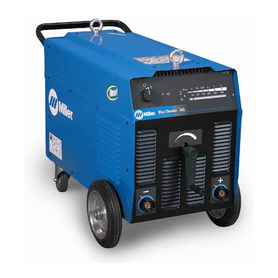
Summarization of Contents
SECTION 1 - SAFETY PRECAUTIONS - READ BEFORE USING
1-1. Symbol Usage
Explains the meaning and usage of warning symbols in the manual.
1-2. Arc Welding Hazards
Details hazards associated with arc welding processes and necessary precautions.
1-3. Additional Symbols For Installation, Operation, And Maintenance
Covers additional safety symbols related to operating and maintaining the equipment.
1-4. California Proposition 65 Warnings
Warns about chemicals in exhaust and battery components.
1-5. Principal Safety Standards
Lists key safety standards and their sources for reference.
1-6. EMF Information
Discusses electromagnetic fields and minimizing exposure during welding.
SECTION 2 - DEFINITIONS
2-1. Warning Label Definitions (For Wordless Labels)
Explains the meaning of various warning labels found on the equipment.
2-2. WEEE Label (For Products Sold Within The EU)
Explains the Waste Electrical and Electronic Equipment label for EU products.
2-3. Manufacturer's Rating Label
Details the machine's specifications and rating information.
2-4. Symbols And Definitions
Provides a comprehensive list and explanation of symbols used in the manual.
SECTION 3 - INSTALLATION
3-1. Specifications
Lists detailed technical specifications for each model of the unit.
3-2. Volt-Ampere Curves
Illustrates the normal minimum and maximum voltage and amperage output capabilities.
3-3. Duty Cycle and Overheating
Explains duty cycle ratings and how to prevent overheating.
3-4. Selecting A Location
Provides guidelines for choosing a suitable location for the welding unit.
3-5. Tipping
Warns against moving or operating the unit where it could tip.
3-6. Weld Output Terminals and Selecting Cable Sizes
Details weld output terminals and guidance on selecting appropriate cable sizes.
3-7. Typical Connections For Stick (SMAW) Welding
Shows a typical connection diagram for Stick (SMAW) welding.
3-8. Positioning Jumper Links
Instructions on how to position jumper links for voltage selection.
3-9. Electrical Service Guide
Provides recommendations for fuses, circuit breakers, and conductor sizes.
3-10. Connecting Input Power
Step-by-step instructions for connecting the unit to the input power supply.
SECTION 4 - OPERATION
4-1. Controls
Identifies and explains the function of the unit's controls and indicators.
SECTION 5 - MAINTENANCE AND TROUBLESHOOTING
5-1. Routine Maintenance
Outlines regular maintenance tasks to keep the equipment in good working order.
5-2. Troubleshooting
Provides solutions for common problems encountered during operation.
SECTION 6 - ELECTRICAL DIAGRAMS
Figure 6-1. Circuit Diagram For Blue Thunder 253
Provides the electrical circuit diagram for the Blue Thunder 253 model.
Figure 6-2. Circuit Diagram For Blue Thunder 343 And 443 Models (380/520 V)
Shows the electrical circuit diagram for Blue Thunder 343/443 models operating at 380/520V.
Figure 6-3. Circuit Diagram For Blue Thunder 343 And 443 Models (230/400 V)
Displays the electrical circuit diagram for Blue Thunder 343/443 models operating at 230/400V.
Figure 6-4. Circuit Diagram For Blue Thunder 403
Presents the electrical circuit diagram for the Blue Thunder 403 model.
SECTION 7 - PARTS LIST
Figure 7-1. Blue Thunder 253
Shows an exploded view and part list for the Blue Thunder 253 model.
Figure 7-2. Blue Thunder 343
Shows an exploded view and part list for the Blue Thunder 343 model.
Figure 7-3. Blue Thunder 403
Shows an exploded view and part list for the Blue Thunder 403 model.
Figure 7-4. Blue Thunder 443
Shows an exploded view and part list for the Blue Thunder 443 model.


Need help?
Do you have a question about the Blue Thunder 403 and is the answer not in the manual?
Questions and answers