Table of Contents
Advertisement
Quick Links
Advertisement
Table of Contents
Troubleshooting

Related Manuals for Miller PipeWorx 400


Summary of Contents for Miller PipeWorx 400
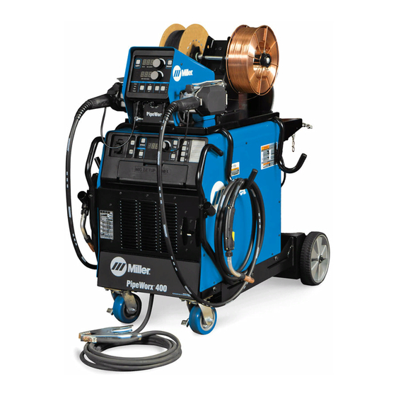
- Page 1 OM-236891AN 2022-11 Processes Multiprocess Welding Description Arc Welding Power Source Wire Feeder PipeWorx 400 Welding System (230/460 And 575 Volt Models) OWNER’S MANUAL For product information, Owner’s Manual translations, and more, visit www.MillerWelds.com...
- Page 2 We know you don’t have time to do it any other way. That’s why when Niels Miller first started building arc welders in 1929, he made sure his products offered long-lasting value and superior quality.
-
Page 3: Table Of Contents
TABLE OF CONTENTS SECTION 1 – SAFETY PRECAUTIONS – READ BEFORE USING..............1 Symbol Usage . - Page 4 Basic Parameters For PipeWorx 400 ........
-
Page 5: Section 1 - Safety Precautions - Read Before Using
SECTION 1 – SAFETY PRECAUTIONS – READ BEFORE USING Protect yourself and others from injury—read, follow, and save these important safety precautions and operating instructions. 1-1. Symbol Usage DANGER! – Indicates a hazardous situation which, if not avoided, will result in death or serious injury. The possible hazards are shown in the adjoining symbols or explained in the text. - Page 6 HOT PARTS can burn. WELDING can cause fire or explosion. � Do not touch hot parts bare handed. � Allow cooling period before working on equipment. Welding on closed containers, such as tanks, drums, or pipes, can cause them to blow up. �...
-
Page 7: Additional Hazards For Installation, Operation, And Maintenance
� Never weld on a pressurized cylinder—explosion will result. CYLINDERS can explode if � Use only correct compressed gas cylinders, regulators, hoses, damaged. and fittings designed for the specific application; maintain them Compressed gas cylinders contain gas under high and associated parts in good condition. pressure. -
Page 8: California Proposition 65 Warnings
� To reduce possible interference, keep weld cables as short as ARC WELDING can cause possible, close together, and down low, such as on the floor. interference. � Locate welding operation 100 meters from any sensitive electronic equipment. � Electromagnetic energy can interfere with sensitive electronic equipment such as microprocessors, �... -
Page 9: Section 2 - Safety Precautions - Read Before Using
SECTION 2 – SAFETY PRECAUTIONS – READ BEFORE USING Protect yourself and others from injury—read, follow, and save these important safety precautions and operating instructions. 2-1. Symbol Usage DANGER! – Indicates a hazardous situation which, if not avoided, will result in death or serious injury. The possible hazards are shown in the adjoining symbols or explained in the text. -
Page 10: California Proposition 65 Warnings
� Allow cooling period before working on equipment. READ INSTRUCTIONS. � Read and follow all labels and the Owner’s Manual HIGH PRESSURE FLUIDS can injure carefully before installing, operating, or servicing or kill. unit. Read the safety information at the beginning of the manual and in each section. -
Page 11: Section 3 - Consignes De Sécurité - Lire Avant Utilisation
SECTION 3 – CONSIGNES DE SÉCURITÉ - LIRE AVANT UTILISATION Pour écarter les risques de blessure pour vous-même et pour autrui — lire, appliquer et ranger en lieu sûr ces consignes relatives aux précautions de sécurité et au mode opératoire. 3-1. - Page 12 � S’assurer que tous les panneaux et couvercles sont correctement LES ACCUMULATIONS DE GAZ en place. risquent de provoquer des blessures � Fixer le câble de retour de façon à obtenir un bon contact métal- ou même la mort. métal avec la pièce à souder ou la table de travail, le plus près possible de la soudure.
-
Page 13: Symboles De Dangers Supplémentaires En Relation Avec L'installation, Le Fonctionnement Et La Maintenance
� Brancher le câble de masse sur la pièce le plus près possible de � Les porteurs d’implants médicaux doivent consulter leur médecin la zone de soudage pour éviter le transport du courant sur une lon- et le fabricant du dispositif avant de s’approcher de la zone où se gue distance par des chemins inconnus éventuels en provoquant déroule du soudage à... - Page 14 � Affûter l'électrode au tungstène uniquement à la meuleuse dotée LIRE LES INSTRUCTIONS. de protecteurs. Cette manœuvre est à exécuter dans un endroit sûr lorsque l'on porte l'équipement homologué de protection du vi- � Lire et appliquer les instructions sur les étiquettes sage, des mains et du corps.
-
Page 15: Proposition Californienne 65 Avertissements
3-4. Proposition californienne 65 Avertissements AVERTISSEMENT – Ce produit peut vous exposer à des pro- Pour plus d’informations, consulter www.P65Warnings.ca.gov. duits chimiques tels que le plomb, reconnus par l’État de Californie comme cancérigènes et sources de malforma- tions ou d’autres troubles de la reproduction. 3-5. -
Page 16: Section 4 - Consignes De Sécurité - Lire Avant Utilisation
SECTION 4 – CONSIGNES DE SÉCURITÉ - LIRE AVANT UTILISATION Pour écarter les risques de blessure pour vous-même et pour autrui — lire, appliquer et ranger en lieu sûr ces consignes relatives aux précautions de sécurité et au mode opératoire. 4-1. -
Page 17: Proposition Californienne 65 Avertissements
� Suivre les consignes du Manuel des applications pour l’équation LA VAPEUR ET LE LIQUIDE DE de levage NIOSH révisée (Publication Nº94– 110) lors du levage REFROIDISSEMENT CHAUD peuvent manuelle de pièces ou équipements lourds. provoquer des brûlures. L’EMPLOI EXCESSIF peut Un tuyau peut se rompre lorsque le liquide de re- SURCHAUFFER L’ÉQUIPEMENT. - Page 18 � Complete Parts List is available at www.MillerWelds.com OM-236891 Page 14...
-
Page 19: Section 5 - Definitions
Some symbols are found only on CE products. facility. Some symbols are found only on CE products. Wear dry insulating gloves. Do not touch electrode with bare hand. Do not wear wet or damaged gloves. Contact your local recycling office or your local distributor for further information. Safe �... - Page 20 Safe22 201 Turn off power before disassembling torch. Protect yourself from electric shock by insulating yourself from work and ground. � Complete Parts List is available at www.MillerWelds.com Safe19 201 Safe3 201 Do not fuel a hot engine. Do not fuel a hot engine. Do not fuel a hot engine.
- Page 21 = < 60 Always lift and support unit using both handles. Keep angle of lifting Safe Become trained and read the instructions before working on the device less than 60 degrees. � Drive rolls can injure fingers. Complete Parts List is available at www.MillerWelds.com machine or welding.
-
Page 22: Miscellaneous Symbols Definitions
� Complete Parts List is available at www.MillerWelds.com 5-2. Miscellaneous Symbols Definitions Gas Tungsten Arc Welding (GTAW) / High Frequency - Amperage Tungsten Inert Gas General (TIG) Welding Three Phase Static Save To Memory Frequency Convert- er-Transformer- Rectifier Electrode Type A complete Parts List is available at www.MillerWelds.com Hertz Duty Cycle... - Page 23 � Complete Parts List is available at www.MillerWelds.com RMD Process Gas Output Welding (General) Gas Postflow Wire Feed Final Slope Initial Sequence Flux Cored Arc Welding (FCAW) Press Two-Step Trigger Operation (GTAW) To Power Source Touch Start (GTAW) OM-236891 Page 19...
-
Page 24: Section 6 - Specifications
Information About Default Weld Parameters And Settings NOTICE – Each welding application is unique. Although certain Miller Electric products are designed to determine and default to certain typical welding parameters and settings based upon specific and relatively limited application variables input by the end user, such default settings are for reference purposes only;... - Page 25 B. Dimensions And Weight Hole Layout Dimensions 19.5 in. (495 mm) 31.75 in. (806 mm) 16.875 in. (424 mm) 31.75 in. (806 mm) 16 in. (406.4 mm) 28.5 in. 5/16-18 in. UNC thread (724 mm) Weight 225 lb (102 kg) 19.5 in.
-
Page 26: Environmental Specifications
6-5. Environmental Specifications A. Power Source IP Rating B. IP Rating IP Rating IP23 This equipment is designed for outdoor use. C. Wire Feeder IP Rating D. IP Rating IP Rating IP21 This equipment is designed for indoor use and is not intended to be used or stored outside. E. -
Page 27: Mig Duty Cycle And Overheating
6-6. MIG Duty Cycle and Overheating Duty Cycle is percentage of 10 minutes that unit can weld at rated load without overheating. If unit overheats, thermostat(s) opens, output stops, and cooling fan runs. Wait fifteen minutes for unit to cool. Reduce amperage or duty cycle before welding. -
Page 28: Tig Duty Cycle And Overheating
6-7. TIG Duty Cycle and Overheating Duty Cycle is percentage of 10 minutes that unit can weld at rated load without overheating. If unit overheats, thermostat(s) opens, output stops, and cooling fan runs. Wait fifteen minutes for unit to cool. Reduce amperage or duty cycle before welding. -
Page 29: Stick Duty Cycle And Overheating
6-8. Stick Duty Cycle and Overheating Duty Cycle is percentage of 10 minutes that unit can weld at rated load without overheating. If unit overheats, thermostat(s) opens, output stops, and cooling fan runs. Wait fifteen minutes for unit to cool. Reduce amperage or duty cycle before welding. -
Page 30: Section 7 - Installation
SECTION 7 – INSTALLATION 7-1. Selecting A Location Movement Do not move or operate unit where it could tip. Location And Airflow Special installation may be required where gasoline or vola- tile liquids are present - see NEC Article 511 or CEC Section 1 Lifting Eye 2 Lifting Forks Use lifting eye or lifting forks to move unit. -
Page 31: Remote 14 Accessory Receptacle Information
7-2. Remote 14 Accessory Receptacle Information If a remote control is connected to the Remote 14 receptacle, the unit will automatically adjust output control to a primary/secondary configura- tion. In this configuration, the Amperage Adjust knob on the unit becomes the primary and sets the maximum amperage output of the unit. The remote control becomes the secondary and provides an amperage range of 0 to 100% based on the Amperage Adjust knob setting. -
Page 32: Turning On Remote 14 Receptacle Control For Stick
7-3. Turning On Remote 14 Receptacle Control For Stick Turn Off welding power source, disconnect input power, and check voltage on input capacitors ac- cording to Section 9-3 before proceeding. When this control is active and a current/ contactor control is connected to the Remote 14 receptacle on the power source front pan- el, the contactor and primary/secondary am- perage control will function in both TIG and... -
Page 33: Changing Wire Feed Speed From Inches Per Minute (Ipm) To Meters Per Minute (Mpm)
7-4. Changing Wire Feed Speed From Inches Per Minute (IPM) To Meters Per Minute (MPM) Turn Off welding power source, disconnect input power, and check voltage on input capacitors ac- cording to Section 9-6 before proceeding. 1 PipeWorx Feeder 2 Operator Interface Board 3 Dip Switch Remove feeder wrapper. -
Page 34: Remote 14 Wire Feeder Control Receptacle Information
7-5. Remote 14 Wire Feeder Control Receptacle Information Remote 14 Feeder Control Socket* Socket Information 8, 12 24 volts AC. Protected by supplementary pro- tector CB2. 24 VOLTS AC 24 volts AC return. Connected to chassis com- mon. Completes 24 volts AC power supply cir- cuit to feeder. -
Page 35: Supplementary Protector Cb2
7-6. Supplementary Protector CB2 1 Supplementary Protector CB2 CB2 protects the 24 volts ac power supply to the wire feeder (see Section7-5). Press button to reset supplementary protector. 805 298-A OM-236891 Page 31... -
Page 36: Volts Ac Single Receptacle Rc2 And Supplementary Protector
7-7. 115 Volts AC Single Receptacle RC2 And Supplementary Protector 1 115V 10A AC Receptacle RC2 � RC2 is a designated use receptacle in- tended only for supplying AC power to a PipeWorx cooler. Power is available at receptacle RC2 only when the power source is on. -
Page 37: Lifting Eye On Power Source
7-8. Lifting Eye On Power Source Turn Off welding power source, disconnect input power. 1 Lifting Eye The wire feeder allows access to the lifting eye on the power source. The entire welding system as shown with ca- ble hangers, cooler with coolant, dual feeder, and running gear can be lifted with the lifting eye. -
Page 38: Selecting Input Voltage (230/460 Volt Models Only)
7-9. Selecting Input Voltage (230/460 Volt Models Only) Have only qualified persons per- form this procedure. Disconnect and lockout/tagout in- put power before removing side panel. Follow established proce- dures regarding the installation removal lockout/tagout devices. Turn Off welding power source, disconnect input power, and check voltage on input capacitors ac- cording to Section 9-6 before... -
Page 39: Electrical Service Guide
7-10. Electrical Service Guide Failure to follow these electrical service guide recommendations could create an electric shock or fire hazard. These recommen- dations are for an individual branch circuit sized for the rated output and duty cycle of one welding power source. In individual branch circuit installations, the National Electrical Code (NEC) allows the receptacle or conductor rating to be less than the rating of the circuit protection device. -
Page 40: Connecting 3-Phase Input Power
7-11. Connecting 3-Phase Input Power GND/PE Earth Ground Input5 2016 −06 − Ref. 803 766-C / 805 146-A OM-236891 Page 36... - Page 41 tools/ 5/16 in. flathead philips head wrench steelbrush nutdriver crescent wrench chippinghammer Section 7-10. Conductors must comply with welding power source line terminals. Turn Off welding power source, and national, state, and local electrical codes. If check voltage on input capacitors knife steelbrush nutdriver...
-
Page 42: Installing Optional Handles, Running Gear And Cooler
7-12. Installing Optional Handles, Running Gear And Cooler A. Installing Running Gear and Cooler Turn Off welding power source, disconnect input power. 1 Running Gear 234359 2 Cooler 3 Wheel 163463 (2) 4 Flat Washer 602250 (4) 5 Retaining Ring 121614 (2) Install wheels on cylinder tray as shown. - Page 43 B. Installing Handles Turn Off welding power source, disconnect input power. 1 Handle Bracket 2 Gun Holder Assembly (2) 3 Screw 195666 (4) 4 Handle (2) 5 Tube Cap (4) Install tube caps into ends of handles. Remove 5 screws above louvered panel on front of power source.
-
Page 44: Assembling And Installing Cable Hanger
7-13. Assembling And Installing Cable Hanger 1 Bracket 2 Tube Cap (4) 3 Cable Holder Tube (2) Install caps in tubes. Assemble cable holder tubes to bracket us- ing supplied hardware. Place cable holder assembly on top of power source or cart and set wire feeder on cable hanger. -
Page 45: Proper Ring Terminal Connection To Volt Sense Lead
7-14. Proper Ring Terminal Connection To Volt Sense Lead tools/ helmet weldshield faceshield en_wrench allen_set flathead philips head wrench crescent wrench chvise needlenose knife steelbrush nutdriver popriveter chippinghammer 239 780-B tools/ olderiron heavy-duty workclamp light-duty workclamp wirecutter frontcutter stripcrimp sealant_1 tape If volt sense lead is cut or broken at end with 1 Jacket... -
Page 46: Selecting Cable Sizes
7-16. Selecting Cable Sizes* NOTICE – The Total Cable Length in Weld Circuit (see table below) is the combined length of both weld cables. For example, if the power source is 100 ft (30 m) from the workpiece, the total cable length in the weld circuit is 200 ft (2 cables x 100 ft). Use the 200 ft (60 m) column to determine cable size. -
Page 47: Connecting Weld Output Cables
7-18. Connecting Weld Output Cables Do not place anything between weld cable terminal and copper bar. Incorrect Installation 803 778-B 3/4 in. (19 mm) 2 Supplied Weld Output Terminal Nut weld cable terminal is tight against copper Turn off power before connecting to ps head wrench crescent wrench... -
Page 48: Typical Connection Diagram For Mig (Gmaw) Equipment With Feeder On Power Source
7-19. Typical Connection Diagram For MIG (GMAW) Equipment With Feeder On Power Source 805144-C 7 Gas Cylinder hose to gas solenoid connector on rear of Do not put feeder where welding feeder or Y-hose for dual wire feeder. wire hits cylinder. Connect 14-pin plug to rear of power source, Do not move or operate equipment and connect 14-socket plug to rear of wire... -
Page 49: Typical Connection Diagram For Mig (Gmaw) Equipment With Feeder On Cart
7-20. Typical Connection Diagram For MIG (GMAW) Equipment With Feeder On Cart 805317-C Locate end of composite cable where gas gas hose to gas solenoid connector on rear Do not put feeder where welding hose extends out of sleeve approximately of feeder or Y-hose for dual wire feeder. -
Page 50: Wire Feeder Rear Panel Connections And Rotating Drive Assembly
7-21. Wire Feeder Rear Panel Connections And Rotating Drive Assembly Desactive la energía antes de con- ectar a los bornes de la salida de soldadura o receptáculos. Una conexión incorrecta de los ca- bles de soldadura puede causar un calor excesivo e iniciar un incen- dio, o dañar su máquina. -
Page 51: Gun Trigger Receptacle
7-22. Gun Trigger Receptacle 1 Left Gun Trigger Receptacle RC2 2 Right Gun Trigger Receptacle RC3 (Dual Model Only) Connect gun trigger plug to appropriate re- ceptacle on feeder. 805 154-A OM-236891 Page 47... -
Page 52: Installing Welding Gun
7-23. Installing Welding Gun 1 Power Clamp Knob 2 Gun Locking Tab 3 Power Pin Groove 4 Gun Connection End Installing gun with Accu-Mate connection Loosen power clamp knob to allow power pin of gun to clear the gun locking tab. Push power pin into power clamp as far as possible to align the groove in the power pin of the gun with the gun locking tab. -
Page 53: Installing And Threading Welding Wire
7-24. Installing And Threading Welding Wire A. Installing Wire Spools And Drive Rolls tools/ allen_wrench allen_set flathead philips head wrench crescent wrench tools/ tools/ tools/ 156 929 A / 150 922 / 156 930 / 804 743 A 3/16, 5/64 in. 15/16, 3/8 in. - Page 54 B. Adjusting Drive Rolls No Wire Slip Wire Slips NONCONDUCTIVE NONCONDUCTIVE SURFACE SURFACE tools/ allen_wrench allen_set flathead philips head wrench crescent wrench tools/ tools/ tools/ 3/16, 5/64 in. 15/16, 3/8 in. pliers needlenose allen_wrench allen_set 4 Drive Rolls flathead philips head cover.
-
Page 55: Voltage Sensing Lead And Work Cable Connections For Multiple Welding Arcs
7-25. Voltage Sensing Lead And Work Cable Connections For Multiple Welding Arcs A. Ideal Setup 805289-C welding system. Use of this lead is critical supporting separate voltage feedback to the 1 Welding Power Source for stable welding performance. welding power sources. The most accurate 2 Composite Cable voltage sensing may not be achieved due to voltage drops in the workpiece. - Page 56 B. Bad Setup 805290-C 1 Welding Power Source This arrangement is a bad setup due to sources will not be correct at either sense sensing leads being directly in the current lead and result in poor arc starts and arc 2 Composite Cable flow path of the welding arc.
-
Page 57: Arranging Welding Cables To Reduce Welding Circuit Inductance
7-26. Arranging Welding Cables To Reduce Welding Circuit Inductance Ideal 1 Welding Power Source 2 Composite Cable 3 Work Cable 4 Volt Sense Lead 5 Wire Feeder 6 Workpiece The method used to arrange cables has a significant affect on welding performance. As an example, Pro-Pulse and RMD welding processes can produce high welding circuit inductance depending on cable length and... -
Page 58: Typical Connection Diagram For Stick (Smaw) Equipment
7-27. Typical Connection Diagram For Stick (SMAW) Equipment 1 Welding Power Source 2 Work (-) Weld Cable 3 Stick (+) Weld Cable 4 Workpiece 5 Electrode Holder 6 Volt Sense Lead � Attach volt sense lead to work clamp and attach work clamp as close to arc as possible. -
Page 59: Typical Connection Diagram For Two Piece Air-Cooled Tig (Gtaw) Torch(Using Gas Solenoid Inside Power Source)
7-28. Typical Connection Diagram For Two Piece Air-Cooled TIG (GTAW) Torch(Using Gas Solenoid Inside Power Source) 1 Welding Power Source 2 Gas Hose 3 TIG (-) Weld Cable 4 Work (+) Weld Cable 5 Workpiece 6 TIG Torch 7 Volt Sense Lead 8 Remote Foot Control (Optional) �... -
Page 60: Typical Connection Diagram For One Piece Air-Cooled Tig (Gtaw) Torch(Using Gas Solenoid Inside Power Source)
7-29. Typical Connection Diagram For One Piece Air-Cooled TIG (GTAW) Torch(Using Gas Solenoid Inside Power Source) 1 Welding Power Source 2 Gas Hose 237 415 (Short Black Hose Supplied With Power Source) 3 TIG Block (Customer Supplied) 4 TIG (-) Weld Cable 5 Work (+) Weld Cable 6 Workpiece 7 TIG Torch... -
Page 61: Typical Connection Diagram For Liquid-Cooled Tig (Gtaw) Torch (Using Gas Solenoid Inside Power Source)
7-30. Typical Connection Diagram For Liquid-Cooled TIG (GTAW) Torch (Using Gas Solenoid Inside Power Source) 1 Welding Power Source 2 Gas Hose 3 TIG Block (Customer Supplied) 4 Coolant Return Hose 237416 (Short Red Hose Supplied With Cooler) 5 TIG (-) Weld Cable 6 Coolant Supply Hose 7 Work (+) Weld Cable 8 Workpiece... -
Page 62: Section 8 - Operation
Only dual shielded wire is recommended for the PipeWorx 400. A gas mixture or wire diameter selection is not required. See wire manufacturer for the recommended gas mixture. The 0.035 to 0.062 wire sizes can be used in the process. - Page 63 Purge Method for energizing the gas valve(s) to purge gas lines before welding and to preset gas pressure at the regu- lator (see Section 8-7, 8-11). RMD stands for Regulated Metal Deposition, a precisely controlled short-circuit transfer process. Benefits of RMD are well suited to root pass welding on pipe, improves gap filling and spatter reduction.
-
Page 64: Welding Power Source Controls
8-2. Welding Power Source Controls A. Front Panel Controls 252 611-A 6 Stick Process Select Button 13 Wire Type Select Button � Only illuminated controls can be 7 Stick Electrode Type Select Button 14 Wire Diameter Select Button changed or adjusted. 8 Ammeter Display 15 Gas Type Select Button 1 Memory Card Busy Indicator... - Page 65 B. Memory Card Slot 1 Memory Card Slot providing custom MIG type weld process da- own personal settings. Push in and release ta, and loading firmware updates to the unit. the card edge to eject it from the slot. This is the memory card slot. A memory card If the power source has multiple users, each can be inserted into the slot and used for user may use a card to store and load their...
- Page 66 D. Using Optional Memory Card 1 Memory Card Insertion a. Lift and hold memory card access cover open. b. Insert memory card into slot (push card all the way into slot and then release). c. Close memory card access cover. 2 Memory Card Removal a.
- Page 67 F. Stick And TIG Welding Process Controls 1 Stick Process Select Button Press and release this button to activate the stick welding process controls. The STICK text below the button illuminates as well as the active stick electrode type text and the swoosh above the amperage adjust knob. The operator must select the desired stick electrode type and adjust the amperage knob to the appropriate setting within a range from 40 to 400 amps.
- Page 68 G. MIG Welding Process Controls � The reference to left side feeder controls or left side gun trigger applies to either a single feeder or dual feeder. The reference to right side feeder controls or right side gun trigger only applies to a dual feeder. The controls in the MIG setup panel are only active when in the MIG process.
-
Page 69: Stick Process Selection Setup Example
8-3. Stick Process Selection Setup Example 252 611-A 1 Stick Process Active 3 Amperage Setting 350A � Only illuminated controls can be 2 EXX10 Electrode Type Selected 4 Memory Location 1 Active changed or adjusted. 8-4. TIG Process Selection Setup Example 252 611-A 1 TIG Process Active 3 Amperage Setting 350A... -
Page 70: Mig Process Selection Setup Example 1
8-5. MIG Process Selection Setup Example 1 252 611-A 2 Carbon Steel Wire Type Selected 5 Trigger Select On � Only illuminated controls can be 3 0.035 Wire Diameter Selected 6 Side Select Left changed or adjusted. 4 C8-C15 Gas Type Selected 7 Memory Location 3 Active 1 MIG Process Active OM-236891 Page 66... -
Page 71: Mig Process Selection Setup Example 2
8-6. MIG Process Selection Setup Example 2 252 611-A 2 Stainless Steel Wire Type Selected 5 Trigger Select On � Only illuminated controls can be 3 0.035 Wire Diameter Selected 6 Side Select Left changed or adjusted. 4 TRI-H Gas Type Selected 7 Memory Location 4 Active 1 Pro-Pulse MIG Process Active OM-236891 Page 67... -
Page 72: Wire Feeder Controls
8-7. Wire Feeder Controls A. Front Panel Controls 252 614-A 5 ACCU-POWER Indicator (Optional) 11 Jog Button � Only illuminated controls can be 6 Wire Feed Speed Display 12 Trigger Hold Select Button changed or adjusted. 7 Wire Feed Speed Adjust Knob 1 Left Side Controls Select Button 13 Purge Button 8 MPM/IPM Indicator... - Page 73 1 Left Side Controls Select Button Press and release this button to activate the wire feeder left side controls. The LEFT text below the button will illuminate and the swooshes above the volts/arc length adjustment knob and wire feed speed adjustment knob will illuminate. See Section 8-2 for the procedure to select the appropriate MIG process type parameters.
- Page 74 Auto Jog � Pressing and releasing the jog and trigger hold buttons simultaneously will activate the auto jog function. Depending on the active side se- lection, the left or right (dual feeder only) side will automatically jog a preset amount of wire. The volts/arc length display will count down in 0.1 ft or 0.01 m decrements starting at the preset wire length.
-
Page 75: Preflow And Postflow Adjustment
8-8. Preflow And Postflow Adjustment 252 614-A Postflow 4 Release the Purge button. � Postflow will not function without an 5 Adjust preflow time to desired value by arc initiation. For TIG, the postflow time is a function of rotate the Wire Feed Speed knob. output current where the minimum time is 8 Preflow and Postflow times can be config- seconds from 0 to 175 amps and increases... -
Page 76: Wire Feeder Left Side Active Setup Example
8-9. Wire Feeder Left Side Active Setup Example 16.5 252 614-A 1 Left Side Controls Active 3 Trigger Hold Off � Only illuminated controls can be 2 MIG Process Selected 4 Memory Location 1 Active changed or adjusted. OM-236891 Page 72... -
Page 77: Wire Feeder Right Side Active Setup Example (Dual Feeder Only)
8-10. Wire Feeder Right Side Active Setup Example (Dual Feeder Only) 252 614-A 1 Right Side Controls Active 3 Trigger Hold On � Only illuminated controls can be 2 Pulse Process Selected 4 Memory Location 2 Active changed or adjusted. OM-236891 Page 73... -
Page 78: Wire Feeder Non-Mig Setup Example
8-11. Wire Feeder Non-MIG Setup Example 252 614-A 1 Non-MIG Process Selected � Only illuminated controls can be 2 Memory Location 3 Active changed or adjusted. OM-236891 Page 74... -
Page 79: Wire Feeder Timed Purge Example
8-12. Wire Feeder Timed Purge Example 252 614-A 1 Purge And Trigger Hold Buttons Pressed 2 Purge Time Setting Adjustment Knob � Only illuminated controls can be Simultaneously 3 Purge Time Remaining Display changed or adjusted. OM-236891 Page 75... -
Page 80: Wire Feeder Auto Jog Example
8-13. Wire Feeder Auto Jog Example 15.3 252 614-A 1 Jog And Trigger Hold Buttons Pressed 3 Jog Feet Remaining Display � Only illuminated controls can be Simultaneously 4 Jog Wire Feed Speed Adjustment Knob changed or adjusted. 5 Jog Wire Feed Speed Display 2 Jog Feet Adjustment Knob OM-236891 Page 76... -
Page 81: Basic Parameters For Pipeworx 400
8-14. Basic Parameters For PipeWorx 400 Steel Wire Size Wire Feed Speed Process Arc Length Shielding Gas in. (mm) IPM (mpm) 100-350 w/200 Nominal +3.0 to -3.0 .035 (0.9) C8 - C15 (2.5-8.9 w/5.1 Nominal) w/zero Nominal 100-350 w/200 Nominal +3.0 to -3.0... - Page 82 Steel Wire Size Wire Feed Speed Process Arc Length Shielding Gas in. (mm) IPM (mpm) 100-780 w/350 Nominal +3.0 to -3.0 .035 (0.9) C8 - C15 (2.5-19.8 w/8.9 Nominal) w/zero Nominal 100-780 w/300 Nominal +3.0 to -3.0 .040 (1.0) C8 - C15 ProPulse Steel Using A (2.5-19.8 w/7.6 Nominal) w/zero Nominal...
- Page 83 Stainless Steel Wire Size Wire Feed Speed Process Arc Length Shielding Gas in. (mm) IPM (mpm) 100-350 w/200 Nominal +3.0 to -3.0 .035 (0.9) (2.5-8.9 w/5.1 Nominal) w/zero Nominal 100-350 w/200 Nominal .035 (0.9) +3.0 to -3.0 98/2 Ox (2.5-8.9 w/5.1 Nominal) 100-350 w/200 Nominal +3.0 to -3.0 .035 (0.9)
- Page 84 Stainless Steel Wire Size Wire Feed Speed Process Arc Length Shielding Gas in. (mm) IPM (mpm) 100-780 w/250 Nominal +3.0 to -3.0 .035 (0.9) (2.5-19.8 w/6.4 Nominal) w/zero Nominal 100-780 w/250 Nominal +3.0 to -3.0 .035 (0.9) 98/2 Ox (2.5-19.8 w/6.4 Nominal) w/zero Nominal 100-780 w/250 Nominal +3.0 to -3.0...
- Page 85 Stainless Steel 100-780 w/200 Nominal +3.0 to -3.0 .035 (0.9) (2.5-19.8 w/5.1 Nominal) w/zero Nominal 100-780 w/200 Nominal +3.0 to -3.0 .035 (0.9) 98/2 Ox (2.5-19.8 w/5.1 Nominal) w/zero Nominal 100-780 w/200 Nominal +3.0 to -3.0 .035 (0.9) Tri-H (2.5-19.8 w/5.1 Nominal) w/zero Nominal 100-780 w/200 Nominal +3.0 to -3.0...
-
Page 86: Lift-Arc And Hf Tig Start Procedures
8-15. Lift-Arc And HF TIG Start Procedures ® Lift-Arc Start ® When Lift-Arc button light is On, start arc as Lift-Arc® Start Method ® follows: 1 TIG Electrode 2 Workpiece Touch tungsten electrode to workpiece at weld start point, enable output and shielding 1 −... -
Page 87: Section 9 - Maintenance And Troubleshooting
SECTION 9 – MAINTENANCE AND TROUBLESHOOTING 9-1. Routine Maintenance Disconnect power before maintaining. � Maintain more often during severe conditions. � = Check ◇ = Change � = Clean � = Replace utine Maintenance mplete Parts List is available at www.MillerWelds.com Every 3 Months Disconnect power... -
Page 88: Blowing Out Inside Of Unit
9-2. Blowing Out Inside of Unit Do not remove case when blowing out inside of unit. To blow out unit, direct airflow through front and back louvers as shown. 805142-B 9-3. Restoring Factory Defaults Full System A full factory reset can be accomplished by pressing memory location buttons 1 and 4 on the power source simultaneously for more than four seconds. -
Page 89: Power Source Calibration Procedure
9-5. Power Source Calibration Procedure Only qualified persons should install, operate, maintain, and repair this unit. A. Required Equipment 1 Calibrated DC voltmeter and clamp-on DC ammeter (e.g. Fluke 337) 2 Calibration Card 3 Shorting cable (2/0) B. Calibration Procedure 1 Disconnect cables from all output studs. -
Page 90: Measuring Input Capacitor Voltage In 230/460 Volt Models And 575 Volt Models Eff W/Serial No. Ma380007G
9-6. Measuring Input Capacitor Voltage In 230/460 Volt Models And 575 Volt Models Eff w/Serial No. MA380007G Have only qualified persons per- form this procedure. Disconnect and lockout/tagout in- put power before removing side panel. Follow established proce- dures regarding the installation removal lockout/tagout devices. -
Page 91: Measuring Input Capacitor Voltage In 575 Volt Models Prior To Serial No. Ma380007G
9-7. Measuring Input Capacitor Voltage In 575 Volt Models Prior To Serial No. MA380007G Have only qualified persons per- form this procedure. Disconnect and lockout/tagout in- put power before removing side panel. Follow established proce- dures regarding the installation removal lockout/tagout devices. -
Page 92: Cooler Routine Maintenance
Every Months ◇ Change coolant (if using Miller coolant). *To be done by factory authorized service agent. 805497-A 805497-A 0536 Page 42 OM-270536 Page 42 OM-236891 Page 88... -
Page 93: Coolant Maintenance
9-9. Coolant Maintenance Disconnect cooler plug from weld- ing power source receptacle be- fore maintaining. Dispose of used coolant according to national, state, and local codes. Do not pour down drain. 1 Cooler Housing 2 Cooler Drawer Remove 4 screws from front of cooler hous- ing and slide cooler drawer out. -
Page 94: Welding Power Source And Feeder Diagnostic Help Codes
9-10. Welding Power Source And Feeder Diagnostic Help Codes Display Example Display Code Fault Description Primary Power Circuit Indicates a malfunction in the primary power circuit. If this code appears on the display, contact Over Current the nearest Factory Authorized Service Agent. Temperature Sensor Indicates thermal protection circuitry is malfunctioning. - Page 95 Memory Card Fault Indicates unable to read memory card. Faulty memory card or wrong format. File Read Error Indicates faulty file on memory card. File Write Error Indicates full or faulty memory card. Indicates an invalid file on memory card. The system was able to read the file; however, the con- Invalid File tents of the file were invalid.
-
Page 96: Troubleshooting Welding Power Source/Wire Feeder Issues
9-11. Troubleshooting Welding Power Source/Wire Feeder Issues If the welding power source and wire feeder are NOT responding after everything is connected, follow the items listed below before contacting the nearest factory-authorized service agent: Welding power source is plugged in and there is no power after turning on unit. �... -
Page 97: Welding Power Source Troubleshooting
9-12. Welding Power Source Troubleshooting Trouble Remedy No weld output; unit completely Place line disconnect switch in On position (see Section 7-11). inoperative. Check and replace line fuse(s), if necessary, or reset circuit breaker (see Section 7-11). Check for proper input power connections (see Section 7-11). No weld output;... -
Page 98: Cooler Troubleshooting
9-14. Cooler Troubleshooting Disconnect power before troubleshooting. Trouble Remedy Coolant system does not work. Be sure input power cord is plugged into energized receptacle. Check supplementary protector CB1 at welding power source, and reset if necessary. Motor overheated. Unit starts running when motor has cooled. Have Factory Authorized Service Agent check motor. -
Page 99: Section 10 - Electrical Diagrams
SECTION 10 – ELECTRICAL DIAGRAMS Figure 10-1. Circuit Diagram For Welding Power Source OM-236891 Page 95... - Page 100 278371B OM-236891 Page 96...
- Page 101 OM-236891 Page 97...
- Page 102 Figure 10-2. Circuit Diagram For Single Or Dual Wire Feeder OM-236891 Page 98...
- Page 103 236220G OM-236891 Page 99...
- Page 104 Figure 10-3. Circuit Diagram For Cooler OM-236891 Page 100...
- Page 105 Torch Pump Filter Radiator Flow Indicator Tank Figure 10-4. Flow Diagram For Cooler OM-236891 Page 101...
-
Page 106: Section 11 - High Frequency
SECTION 11 – HIGH FREQUENCY SECTION 1 HIGH FREQUENCY 11-1. Welding Processes Requiring High Frequency SECTION 1 HIGH FREQUENCY 1 High-Frequency Voltage TIG – helps arc jump air gap between torch and workpiece and/or stabilize the arc. 11-2. Installation Showing Possible Sources Of HF Interference 11, 12 Best Practices Not Followed 11, 12... -
Page 107: Recommended Installation To Reduce Hf Interference
11-3. Recommended Installation To Reduce HF Interference Best Practices Followed 50 ft (15 m) 50 ft (15 m) 1 High-Frequency Source (welding power Conduit Joint Bonding and Grounding Ground workpiece if required by codes. source with built-in HF or separate HF Electrically join (bond) all conduit sections 9 Nonmetal Building unit) - Page 108 Notes...
- Page 109 Notes...
- Page 110 Notes...
- Page 111 Effective January 1, 2022 (Equipment with a serial number preface of NC or newer) This limited warranty supersedes all previous Miller warranties and is exclusive with no other guarantees or war- ranties expressed or implied. � Field Options (NOTE: Field options are cov-...
- Page 112 Appleton, WI 54914 USA tact your distributor and/or equipment manu- facturer’s Transportation Department. International Headquarters–USA USA Phone: 920-735-4505 USA & Canada FAX: 920-735-4134 International FAX: 920-735-4125 For International Locations Visit www.MillerWelds.com ORIGINAL INSTRUCTIONS – PRINTED IN USA © Miller Electric Mfg. LLC 2022-11...
Need help?
Do you have a question about the PipeWorx 400 and is the answer not in the manual?
Questions and answers