
Related Manuals for THOMSON HD 150


Summarization of Contents
General Information
About this manual
Details the manual's content, target audience, and importance of reading it before installation.
Target group
Identifies qualified mechanical and electrical personnel as the intended audience for this manual.
Symbols used
Explains the warning symbol used for general warnings or mechanical hazards.
Transport and storage
Provides guidelines for transporting and storing the actuator, including temperature limits and handling precautions.
Packaging
Describes the standard packaging for the actuator and mentions variations for bulk orders.
Disposal
Informs about Thomson's take-back program for used actuators and packaging for professional disposal.
Support
Directs users to Thomson Service Centers and the website for technical support and information.
Safety Precautions
Safety notes
Lists essential safety precautions for installing and operating the actuator, emphasizing qualified personnel.
Standards Compliance
EC Declaration of incorporation of partly completed machinery
Declares compliance with relevant ISO, MD, and RoHS directives for the product.
Installation Procedures
Product label identification
Explains how to find and use the product label for model identification and technical data.
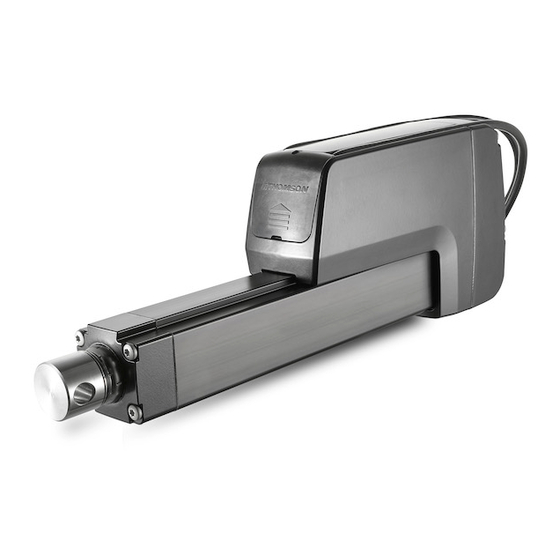
Terminology and component identification
Identifies and illustrates key components and parts of the actuator.
Operation environment specifications
Specifies the environmental conditions for operation, including temperature and protection ratings.
General installation safety notes
Lists critical safety precautions to follow during mechanical installation.
Basic installation considerations
Covers mounting procedures, adapter types, and access for cables and manual override.
Mounting orientation and forces
Details correct and incorrect mounting orientations to handle loads properly and safely.
Cable connector cover plate access
Explains how to access and secure the cable connector cover plate for proper sealing.
Manual override mounting and operation
Describes how to install and operate the manual override feature, including torque limits.
Mounting of optional external limit switches
Details how to mount optional external limit switches in the designated slots.
General electrical installation notes
Emphasizes safety and cable handling for electrical connections.
Fuse size recommendations
Specifies appropriate slow blow fuse sizes for different actuator supply voltages.
Electrical connections
Explains how to connect the power and signal cables to the actuator.
Lead cross sections
Guides on selecting appropriate lead cross sections to prevent voltage drop.
Inrush current considerations
Details the inrush current characteristics for different control options and power supply considerations.
Control options overview
Introduces control options and how to determine the actuator's specific option.
General notes for control options
Provides guidelines for installing and operating control options, focusing on interference reduction.
Determining the control option
Explains how to identify the actuator's control option using the model number and ordering key.
Control option EXX
Details the features and operation of the EXX control option (Electrak monitoring package only).
Control option ELX
Describes the ELX option, adding end-of-stroke indication to the EXX features.
Control option EXP
Explains the EXP option, which adds a potentiometer for position, speed, and direction feedback.
Control option EXD
Details the EXD option, featuring an encoder for position and speed determination.
Control option ELP
Describes the ELP option, combining end-of-stroke indication with potentiometer feedback for position control.
Control option ELD
Details the ELD option, which includes end-of-stroke indication and encoder feedback.
Control option LXX
Explains the LXX option for low-current input signals to control actuator motion.
Control option LLX
Describes the LLX option, adding end-of-stroke indication to the LXX features.
Control option LXP
Details the LXP option, combining LXX features with potentiometer feedback for position control.
Control option CNO
Covers the CNO option for CAN Bus J1939 control and open-loop speed control.
CAN Bus SAE J1939 installation data
Provides wiring guidelines and termination resistor information for CAN Bus J1939.
CAN Bus Communication
Introduction to CANBUS SAE J1939
Introduces the SAE J1939 standard and supported PGNs for Electrak HD actuators.
J1939 NAME defaults
Lists the default J1939 NAME parameters for the Electrak HD actuator.
Address selection for CAN Bus
Explains methods for selecting and managing actuator addresses on a CAN bus network.
Sleep operation mode
Describes the actuator's sleep mode for low power consumption during inactivity.
J1939 actuator control message (ACM)
Details the ACM structure, parameters, and their functions for actuator control.
ACM Position command
Explains the 14-bit signal for setting the target position and its resolution.
ACM Current limit
Describes the 9-bit signal for setting the current limit to prevent motor damage.
ACM Speed command
Details the 5-bit signal used to control the actuator's speed.
ACM Motion enable
Explains the 1-bit signal used to enable or disable actuator motion.
Factory use in ACM
Notes the use of remaining ACM bits for factory calibration.
J1939 actuator feedback message (AFM)
Details the AFM structure and parameters for retrieving actuator feedback data.
AFM Measured position
Explains the 14-bit signal for reporting the actual actuator stroke position.
AFM Measured current
Details the 9-bit signal for reporting the actuator's current draw.
AFM Running speed
Describes the 5-bit signal reporting the actuator's current duty cycle.
AFM Voltage error
Explains the 2-bit signal indicating if operational voltage is outside the allowed range.
AFM Temperature error
Details the 2-bit signal for indicating if operational temperature is outside the allowed range.
AFM Motion flag
Explains the 1-bit signal indicating if the actuator is currently in motion.
AFM Overload flag
Describes the 1-bit signal indicating a current overload condition during the last motion.
AFM Backdrive flag
Details the 1-bit signal indicating unintended positional movement of the extension tube.
AFM Parameter flag
Explains the 1-bit signal for parameters outside the model's allowed range.
AFM Saturation flag
Describes the 1-bit signal indicating the actuator is running near its maximum capability.
AFM Fatal error flag
Details the 1-bit signal indicating the actuator requires service.
Factory use in AFM
Notes the use of remaining AFM bits for factory calibration.
Technical Specifications
Technical data
Presents detailed technical specifications for the Electrak HD actuators, including electrical, mechanical, and environmental data.
Ordering key
Provides a detailed key to understanding the model numbering and configuration options for ordering.
Need help?
Do you have a question about the HD 150 and is the answer not in the manual?
Questions and answers