Table of Contents
Advertisement
Quick Links
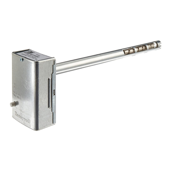
L4064B, L4064R
Universal Combination Fan and
Limit Controllers
APPLICATION
These combination warm air fan and limit controllers
are suitable for various types of forced air heating
systems. The controllers have 2 switches; one which
opens the limit circuit if the plenum temperature
exceeds the preset safety limit; it resets automatically.
The other switch turns the fan on and off. The fan is
turned on and off according to plenum temperature.
The L4064R has a special high temperature range
suitable for gravity heating systems. All models may
be used as limit controllers by wiring only the limit
side. Limit contacts are suitable for both line voltage
and low voltage. For low voltage applications, the
brass jumper must be removed.
OPERATION
As the plenum temperature rises, the coiled bimetal
sensing element of the control warps and
mechanically makes the fan contacts (at the FAN ON
temperature setting). During normal operation, the
call for heat ends before the LIMIT setting is reached
and the fan contacts break as the plenum
temperature falls and the FAN OFF setting is reached.
If the call for heat continues until the temperature in
the plenum rises to the LIMIT setting, the bimetal
element will mechanically break the limit contacts
and de-energize the heating control circuit.
INSTALLATION INSTRUCTIONS
INSTALLATION
When Installing this Product...
1. Read these instructions carefully. Failure to fol-
low them could damage the product or cause a
hazardous condition.
2. Check the ratings given in the instructions and
on the product to make sure the product is suit-
able for your application.
3. Installer must be a trained, experienced service
technician.
4. For 230 VAC application, use of double insu-
lated cable is required.
5. After installation is complete, check out product
operation as provided in these instructions.
WARNING
If limit switch is used on a low voltage
circuit, failure to remove brass jumper can
cause electrical shock hazard and/or
damage to low voltage controls.
CAUTION
1. Disconnect power supply before connecting
wiring to prevent electrical shock or equipment
damage.
2. When connecting cable or conduit to control,
avoid straining the control case.
Follow furnace or burner manufacturer's instructions,
if available. Maximum element temperature is:
L4064B—350 ºF (177 ºC).
L4064R—250 ºF (121 ºC) above limit setting.
Maximum switch temperature is:
L4064B,R—190 ºF (88 ºC).
69-0115-11
Advertisement
Table of Contents

Related Manuals for Honeywell L4064R


Summarization of Contents
Application
Operation
Explains the bimetal element's function and contact operation based on plenum temperature.
Installation Instructions
Installation
Outlines general installation advice, including reading instructions, checking ratings, and installer qualifications.
Warning
Warns about potential shock or damage from a brass jumper in low voltage circuits.
Caution
Advises disconnecting power before wiring and avoiding strain on the control case.
Wiring
Important Wiring Note
Highlights the breakaway brass jumper and its removal for low voltage circuits.
Wiring Connections
Explains how to connect wires using push-in terminals or female receptacles.
Standard Wire Push-in Terminals
Details connecting wires to standard push-in terminals, including wire gauge and insertion.
Female Receptacles
Describes connecting wires to female receptacles using male flag connectors.
Checkout Procedure
Fan Setting Adjustment
Explains how to set the FAN OFF and FAN ON levers for fan operation.
Manual Fan Switch Operation
Describes using the manual fan switch for constant or automatic fan operation.
Limit Setting Adjustment
Details how to set the limit lever for high-limit switch operation to stop the burner.
Need help?
Do you have a question about the L4064R and is the answer not in the manual?
Questions and answers