Advertisement
440 & 450 ELECTRONIC VIBRATION SWITCHES
Installation Manual
Doc#
90018-031 • REV L (April 2016)
1. OVERVIEW
1.1 Introduction
The single setpoint models (SR) contain one
trip limit for shutdown. The optional dual
setpoint models (DR) contain two indepen-
dent trip limits; one for alarm and one for
shutdown. Shutdown and alarm limits are
in engineering units of velocity. In addition,
a 4-20 mA output proportional to vibration
velocity is provided.
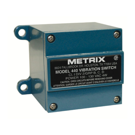
Models 440 and 450 use identical design
and differ only in the enclosure. The model
440 is designed to be used in non-hazardous
or non-incendive hazardous location (Class
I, Division 2, Groups B, C, D, and NEMA
4X). The model 450 is designed to meet
explosion-proof requirements for Class
I, Division 1, Groups B, C, D installations.
Unless otherwise noted, all discussions and
diagrams herein assume the model 440, but
apply equally to the model 450.
1.2 Key Capabilities
•
Shutdown and alarm settings are based
on vibration severity. The internal sen-
sor (unless the external sensor option
has been specified (Ordering Option
I=5 – see note in Section 5.4) is a piezo-
electric crystal with built in microelec-
tronics to reduce noise sensitivity. The
output signal is electronically integrat-
ed to measure and trip on velocity.
•
Calibrated setpoint controls permit set-
point adjustment of vibration velocity
levels up to full scale range. DR model
Advertisement
Table of Contents

Related Manuals for Metrix 450


Summarization of Contents
Overview of Metrix Vibration Switches
Introduction and Model Differences
Explains the purpose of the vibration switches, models (SR/DR), and enclosure variations (440 vs 450).
Key Features and Capabilities
Details features like setpoints, sensor technology, output signal, and adjustable setpoints for vibration monitoring.
User Interface Elements
Describes LEDs, setpoint adjustment knobs, and the time delay setting for user interaction.
Safety Warnings and Precautions
Electrical Shock and Operation Hazards
Warns about shock hazards and emphasizes safe operation according to manual and datasheet specifications.
Mechanical Installation Guidelines
Mounting Location, Axis, and Orientation
Guides on selecting mounting points, understanding the sensitive axis, and choosing optimal orientation.
Surface, Temperature, and Elevation Factors
Covers requirements for mounting surfaces and considerations for temperature and altitude effects on performance.
Cable Management and Sealing
Details wiring practices, conduit use, sealing, and moisture prevention for reliable installation.
Electrical Installation Procedures
Wiring Connections and Terminal Legends
Provides terminal numbering and wiring diagrams for Triac/Analog and Mechanical Relay outputs.
Output Options and Operational Modes
Explains Triac, FET, Relay outputs, latch/auto reset modes, lockout, and 4-20mA output functionality.
Functional Circuitry Explained
Describes the internal signal path from the vibration sensor through signal processing to the output stages.
Control Settings and Calibration
Setting Vibration Trip Points and Time Delays
Guides on adjusting alarm/shutdown setpoints and the built-in time delay for vibration transients.
Testing Procedures and Vibration Measurement
Details how to use the test mode and methods for verifying current vibration levels.
Outline and Dimensions
Model 440 Physical Specifications
Provides detailed dimensions, mounting hole patterns, and connection access for the Model 440.
Model 450 Physical Specifications
Provides detailed dimensions, mounting hole patterns, and connection access for the Model 450.
Wiring Diagrams
Triac/Analog Switch Wiring Schematics
Illustrates electrical connections for models using Triac or Analog switch outputs with AC/DC power.
Mechanical Relay Wiring Schematics
Illustrates electrical connections for models using Mechanical Relay outputs with AC/DC power.
Environmental Information
WEEE Disposal and Compliance
Provides information on the proper disposal of electronic equipment according to WEEE regulations.
Need help?
Do you have a question about the 450 and is the answer not in the manual?
Questions and answers