Table of Contents
Advertisement
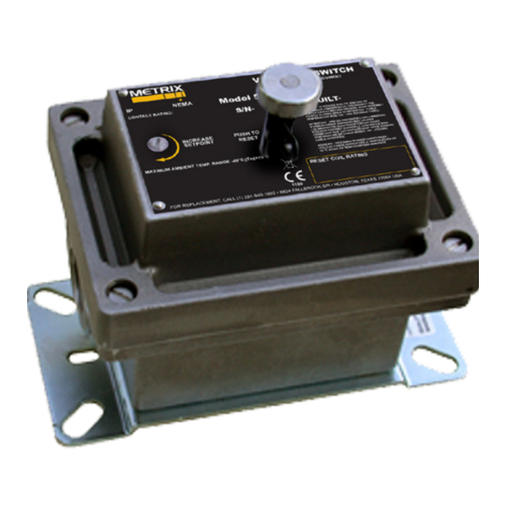
5550 & 5550G MECHANICAL VIBRATION SWITCHES
User Guide / Installation Manual
MODEL 5550
1180
MODEL 5550G
DOC# 1231558 • REV C (November 2017)
1180
The 5550 and 5550G mechanical vibration
switches provide vibration protection for
low- to medium-speed machinery. An inertia
sensitive mechanism activates a snap-action
switch with SPDT output contacts if the vi-
bration exceeds an adjustable setpoint. The
5550 mechanical vibration switch contacts
can be used to activate an alarm or initiate
equipment shutdown. The housing is weath-
erproof with an optional hazardous area
rating. Electrical (remote) reset with start-up
time delay and a second set of SPDT output
contacts to accommodate DPDT needs
(e.g. separate trip and trip light circuits) are
available.
The 5550G uses identical internal mecha-
nisms, but carries an IECEX rating ideal for
IIC gas group applications.
Advertisement
Table of Contents

Related Manuals for Metrix 5550


Summary of Contents for Metrix 5550
- Page 1 5550 & 5550G MECHANICAL VIBRATION SWITCHES User Guide / Installation Manual The 5550 and 5550G mechanical vibration switches provide vibration protection for low- to medium-speed machinery. An inertia sensitive mechanism activates a snap-action switch with SPDT output contacts if the vi- bration exceeds an adjustable setpoint.
-
Page 2: Principles Of Operation
1.2 Typical Application The model 5550 and 5550G mechanical vibration switches are typically used on cooling tower fans and mounted such that loss of a blade will result in significant structural accelera- tion at the switch mounting location (Figure 2). - Page 3 Depending on how the switch is oriented, gravity will act on the trip mechanism’s mov- able mass to either add to or subtract from the spring force. For both model 5550 and 5550G switches, the switch orientation is the direction in which the cover faces. With the...
-
Page 4: Installation
When installing the switches in hazardous atmospheres, refer to Metrix manuals M8905 (5550) and 100356 (5550G) for important safety information. All of these manuals, as well as additional technical resources, are available on our website at www.metrixvibra-... - Page 5 2.1 Maintenance Convenience Versus Measurement Quality While it is desirable to mount the switch in a location in which it can be easily serviced and maintained, this should not be the dominant consideration. The switch serves as a me- chanical sensor and for it to provide suitable machinery protection, it must be mounted in a location and orientation where the machine’s inertial forces during malfunction conditions will be suitably large to trip the switch.
-
Page 6: Side View
Metrix does not recommend installation as shown in Figure 7 unless the machine truly experiences more vibration in the vertical direction than in the horizontal direction, or the 2g / 24V reset coil option is being used (see note in Section 2.4). -
Page 7: Top View
(except in explosion-proof installations) CONDUIT Shaft Radial X Axis BASEPLATE Figure 8: Vertical Machine showing horizontal 5550 mounting orientation and recommended location Doc# 1231558 • REV C (November 2017) Page 7 of 20... - Page 8 The switch can be rotated about its sensitive axis without affecting its operation (Figure 9). Thus, positions 9A, 9B, 9C, and 9D showing the model 5550 switch rotated at 12:00, 3:00, 6:00, and 9:00 positions respectively do not affect the operation of the switch and are pri- marily a matter of preference and serviceability.
- Page 9 Place the cover on the unit and screw tight (model 5550G) or by torqueing the four cover bolts shown in Figure 11 (model 5550 only) to 6-7 ft/lbs. Figure 11: 5550 cover bolts location Doc# 1231558 •...
- Page 10 2.11.1 Ensure the cover is properly tightened The importance or properly tightening cover bolts (5550) or screw-type lid (5550G) per- tains not just to sealing against ignition of a flammable atmosphere outside the switch, but also to prevent dust or moisture ingression to the switch internals.
-
Page 11: Important Safety Information
This practice will provide added protection against moisture ingression over time. Metrix recommends Dow Corning #33 Molykote® Extreme Low Temperature Silicone Grease or equivalent. -
Page 12: Setpoint Adjustment
To verify the factory setpoint, place the switch on a flat surface with the cover facing up. Do not connect any wiring yet. Press the reset plunger (model 5550 only – remove cover on model 5550G) to ensure the switch is in its untripped position (it may have tripped due to shock or vibration incurred during shipping and handling). - Page 13 5550 4.2 In-Situ Setpoint Adjustment The setpoint adjustment is accessible externally on the model 5550 (see Figure 3). For model 5550G, the lid must be removed. Follow the steps below to adjust the setpoint for the par- ticulars of your machine.
- Page 14 4.2.5 Hold the reset plunger (5550) or trip plate (5550G) down and start the machine. When the machine has reached running speed, release the plunger (5550) or trip plate (5550G).
- Page 15 5. ELECTRICAL RESET AND STARTUP DELAY When a reset coil is specified (standard on 5550G, optional on 5550 where ordering option D = 1, 2, 3, or 4), an electrical solenoid mechanism is installed that allows remote reset of the switch when in its tripped position, and initiation of a startup delay when in its untripped position.
- Page 16 5550/5550G to be removed from the machinery shutdown loop. NOTE: The reset coil circuit contains a thermistor that allows the circuit to also function as a startup delay when voltage is continuously applied (see section 5.2).
- Page 17 • Cool-Down Period If the circuit activating the startup delay leaves the voltage continuously applied (as is typical), the thermistor will remain hot until voltage is removed, such as follow- ing a machine trip. Thus, when the thermistor is not allowed to cool to its ambient surroundings, it will shorten the startup delay.
- Page 18 6. DRAWINGS, SPECIFICATIONS, AND ORDERING INFORMATION Unless otherwise noted, all figures and illustrations in this manual depict the model 5550 mechanical switch. The 5550G is identical in terms of its internal mechanisms, but has a different housing that is rated for use in the more stringent IIC gas group.
-
Page 19: Hazardous Area Approvals
UL/CSA Standards: D’ATMOSPHERES (North UL 698 DANGEREUSES COUPER America): UL 508 L’ALIMENTATION ELEC- Models 5550-2XX-XXX or CSA C22.2 No. 25 TRIQUE CIRCUIT AVANT 5550-7XX-XXXZ: CSA C22.2 No. 30 D’OUVRIR COFFRET Class I, Div 1, Groups B,C,D,Class CSA C22.2 No. 14... -
Page 20: Environmental Information
WEEE) should never be disposed of in the public waste stream. The “Crossed-Out Waste Bin” label affixed to this product is a reminder to dispose of this product in accordance with local WEEE regulations. If you have questions about the disposal pro- cess, please contact Metrix Customer Service. info@metrixvibration.com www.metrixvibration.com 8824 Fallbrook Dr.
Need help?
Do you have a question about the 5550 and is the answer not in the manual?
Questions and answers