Advertisement
440 & 450 ELECTRONIC VIBRATION SWITCHES
Installation Manual
Doc#
90018-031 • REV L (April 2016)
1. OVERVIEW
1.1 Introduction
The single setpoint models (SR) contain one
trip limit for shutdown. The optional dual
setpoint models (DR) contain two indepen-
dent trip limits; one for alarm and one for
shutdown. Shutdown and alarm limits are
in engineering units of velocity. In addition,
a 4-20 mA output proportional to vibration
velocity is provided.
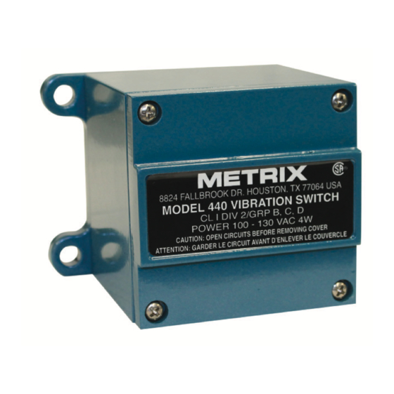
Models 440 and 450 use identical design
and differ only in the enclosure. The model
440 is designed to be used in non-hazardous
or non-incendive hazardous location (Class
I, Division 2, Groups B, C, D, and NEMA
4X). The model 450 is designed to meet
explosion-proof requirements for Class
I, Division 1, Groups B, C, D installations.
Unless otherwise noted, all discussions and
diagrams herein assume the model 440, but
apply equally to the model 450.
1.2 Key Capabilities
•
Shutdown and alarm settings are based
on vibration severity. The internal sen-
sor (unless the external sensor option
has been specified (Ordering Option
I=5 – see note in Section 5.4) is a piezo-
electric crystal with built in microelec-
tronics to reduce noise sensitivity. The
output signal is electronically integrat-
ed to measure and trip on velocity.
•
Calibrated setpoint controls permit set-
point adjustment of vibration velocity
levels up to full scale range. DR model
Advertisement
Table of Contents


Need help?
Do you have a question about the 440 and is the answer not in the manual?
Questions and answers