Metrix Vibralert 5550 Quick Start Manual
Hide thumbs
Also See for Vibralert 5550:
- Installation manual (8 pages) ,
- User manual & installation manual (21 pages)
Advertisement
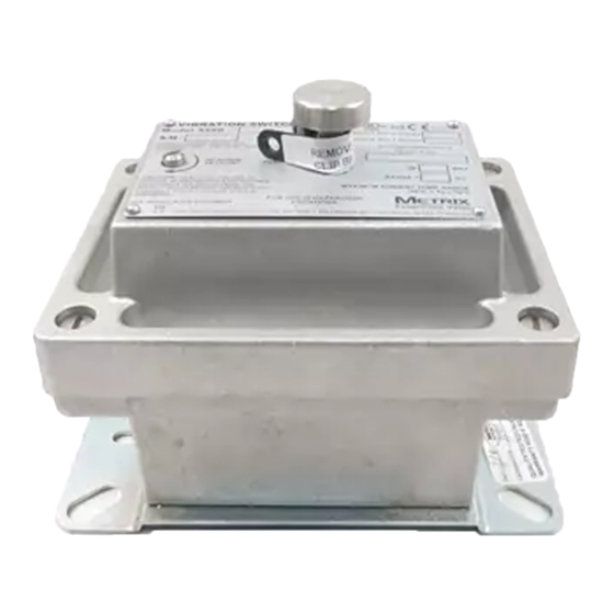
5.563
4.250
SET POINT
ADJUSTMENT
SCREW
1x M20
4X 10-32 UNF
2.313
3.688
THIS DRAWING IS THE SOLE PROPERTY OF
GREAT WESTERN MFG. CO. INC.
AND IS PROTECTED UNDER ALL APPLICABLE
COPYRIGHT LAWS. THIS DRAWING MAY NOT BE
REPRODUCED WITHOUT PRIOR WRITTEN PERMISSION.
WE RESERVE THE RIGHT TO MAKE IMPROVMENTS OR
CHANGES. THIS DRAWING IS LOANED SUBJECT
TO RETURN ON DEMAND.
UNLESS OTHERWISE NOTED DIMS. ARE IN INCHES
AND TOLERANCES ARE AS FOLLOWS:
MACHINING .003
FORMING .015
RESET PUSH
BUTTON
5.130
4.230
DRAWING NUMBER:
028-000-481
MODELED BY:
KLB
CHECKED BY:
DESCRIPTION:
WELDING .060
ANGLES 1
MAT'L:
3003 Alloy
MAT'L #:
PURCHASED
ASSEMBLY .060
A
REV.
ECO NO
REV
DESCRIPTION:
A
Metrix 5550-411-04 Single Pole, Double Throw
DATE:
3/22/2011
DATE:
SCALE:
SIZE
1:4
A
Vibration Switch
VENDOR
MODEL NUMBER
Metrix Instrument Co.
5550-411-04
Metrix Instrument Co.
5550-311-04
Initial Release
RAP
DESCRIPTION
BY
Switch Vibration ATEX SPDT
6.197
SHEET 1 OF 1
6/11/2020
DATE
Advertisement
Table of Contents

Subscribe to Our Youtube Channel
Related Manuals for Metrix Vibralert 5550


Summary of Contents for Metrix Vibralert 5550
- Page 1 AND IS PROTECTED UNDER ALL APPLICABLE COPYRIGHT LAWS. THIS DRAWING MAY NOT BE REPRODUCED WITHOUT PRIOR WRITTEN PERMISSION. WE RESERVE THE RIGHT TO MAKE IMPROVMENTS OR Metrix 5550-411-04 Single Pole, Double Throw MODELED BY: DATE: 3/22/2011 CHANGES. THIS DRAWING IS LOANED SUBJECT TO RETURN ON DEMAND.
-
Page 2: Mechanical Switch
-Lowest cost vibration protection; -Baseplates available to accomodate most previous 5550 Metrix or competitor’s switch models for easy retrofit. -Watertight & optional hazardous area rated enclosure -Options for built-in start up trip delay and/or remote reset. The Model 5550 vibration switch is designed to meet all requirements for me- chanical switches in a single, affordable package. -
Page 3: Specifications
4= 115 VDC EEx d IIB T6 Wiring Entry/Mounting Plate 4= CENELEC Flameproof (See Chart below for E) 1 = 3/4” NPT/Metrix 5173 or 5175 EEx d IIB+H 2 = 3/4” NPT/Metrix 5097; VS-2-EX; 366 Contacts 3 = 3/4” NPT/Metrix 5078; 365 1= SPDT 4*= M20 x 1.5/Metrix 5097;... -
Page 4: Installation
(CW) increases the vibra- competent technical assistance. We encourage you to contact tion setpoint. Metrix Instrument Co. or its local representative if further informa- 2) When the switch is shipped from the factory, the setpoint ad- tion is required. -
Page 5: Wiring Diagram
M20 x 1.5/Metrix 5097; VS-2-EX; 366 DPDT CONTACTS AND RESET COIL OPTIONAL 5= Same as option 4 above with epoxy coated mounting plate M20 X 1.5 / METRIX 5173 or 5175 3/4” NPT / PMC/BETA 440 M20 X 1.5 / METRIX 5078; 365 "...
Need help?
Do you have a question about the Vibralert 5550 and is the answer not in the manual?
Questions and answers