Advertisement
Quick Links
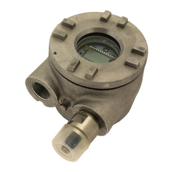
SW6000 SEISMIC VIBRATION SWITCH
Installation Manual
OVERVIEW
The SW6000 Seismic Vibration Switch offers
basic protection against gross changes in
structural seismic acceleration.
This electronic switch is a versatile exces-
sive vibration protection instrument. In its
standard configuration, the SW6000 is an
economical single set point vibration switch
with standard features and packaged in
industrial grade housing with available haz-
ardous area certifications. Fully configured,
the SW6000 provides for local machine
control with optional LCD readout and real
time remote operator interface via a 4-20
mA output.
SUPPLEMENTARY INFORMATION
Refer to Metrix Datasheet #1009462 and
Metrix Installation Manual for Hazardous
Areas #100867 available at www.metrixvi-
bration.com.
Doc#
M9005 • REV N
(May 2017) Page
1 of 12
Advertisement

Related Manuals for Metrix SW6000


Summary of Contents for Metrix SW6000
- Page 1 SW6000 SEISMIC VIBRATION SWITCH Installation Manual OVERVIEW The SW6000 Seismic Vibration Switch offers basic protection against gross changes in structural seismic acceleration. This electronic switch is a versatile exces- sive vibration protection instrument. In its standard configuration, the SW6000 is an...
-
Page 2: Installation
The Stud Mount Unit requires a tapped hole, see Metrix Datasheet (doc #1009462) Option “F” or use a Metrix model 7084 flange mount adapter. If an NPT mounting stud is selected, the stud will tighten before the switch casing touches the machine case. The SW6000 should be hand tightened and then wrench tightened to bring the conduit connections to the ap- propriate location. - Page 3 Figure 2: Wiring Diagram (LCD option not shown) NOTES: Diagrams show all available options, see SW6000 datasheet (doc# 1009462) to verify options on your particular unit. On Single Limit Models, use Load Limit Two (2). Figure 3: Typical Mounting Locations Baseefa Special Conditions for Safe Use: Ambient Operating Temperature: -40°C to +85°C (model without display),...
- Page 4 Polarity does not need to be observed when wiring for DC power. The preferred method of operation is to continuously apply power to the SW6000. If power is to be applied as a part of the machine startup sequence it is advisable to apply power to the SW6000 30 seconds prior to starting the machine in order to allow the electronics circuits to stabilize.
- Page 5 Typical Control Circuits SW6000 w/AC Power Wired to Interrupt Motor Starter (series connection) a. Set each SW6000 for N.C. (normally closed) operation. (See Figure 2) b. M2, M3 and remote reset contacts must each be isolated. Figure 4: Parallel connection of two SW6000 a.
- Page 6 Signal Conditioning Module Output: 4 - 20 mA Source Option The SW6000 can be factory configured to provide a 4 - 20 mA current source output propor- tional to the specified full scale vibration response (velocity or displacement). Figure 5 shows suggested programming for a 4-20 mA receiver (PLC, DCS, monitor or computer).
- Page 7 Ensure that the analyzer is configured with the same frequency response as the SW6000 and with the same unit of measure (i.e. ips pk.). To prevent tampering, there are no user accessible adjustments available for field recalibrating. If recalibration is required, the SW6000 should be returned to the factory for recalibration to a traceable standard.
-
Page 8: User Adjustments
Determining Output Voltage If it is desired to determine either the acceleration or velocity amplitude when one measure- ment is unknown, the following formulas can be employed. V= 3687 x A If g’s (A) are known and you wish to determine the velocity output: D= 19,100 x V If velocity is known and you wish to determine the displacement output: D= 8383... - Page 9 Ensure that the current loop is wired properly and that the total loop resistance does not exceed 600 ohms. The Model SW6000 4-20 mA circuit is a current source. A voltage source (power supply) must not be used in the circuit.
- Page 10 This is due to the settling time of the circuitry in the Model SW6000 switch. If a short startup delay is desired, it is suggested that power first be applied to the unit for a minimum of 20 seconds. Power may also be applied continuously. The limits may need to be reset depending on the particular application.
-
Page 11: Hazardous Area Approvals
HAZARDOUS AREA APPROVALS IECEx Approval IEC Markings: IEC Standards: WARNING-EXPLO- (World) SION HAZARD-DO Ex d IIB + H2 T4 Gb IEC60079-0:2011 NOT DISCONNECT Ta -20°C to +85°C IEC60079-1:2007 WHILE CIRCUIT (no display) IS LIVE UNLESS Ta -10°C to +70°C (display) AREA IS KNOWN IECEx LCI 11.0016X TO BE NON-HAZ-... - Page 12 This electronic equipment was manufactured according to high quality stan- dards to ensure safe and reliable operation when used as intended. Due to its nature, this equipment may contain small quantities of substances known to be hazardous to the environment or to human health if released into the environment.
Need help?
Do you have a question about the SW6000 and is the answer not in the manual?
Questions and answers