
Related Manuals for GE P643


Summarization of Contents
Chapter 1 Introduction
Chapter Overview
General information about the technical manual and an introduction to the device(s) described.
Foreword
Technical description of GE's P642, P643, P645, and instructions for using the device.
Product Scope
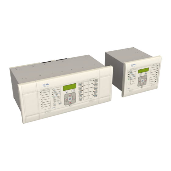
Overview of the P64x range of devices, their features, and model variants.
Features and Functions
Lists the protection and control functions offered by the P64x range of devices.
Compliance
States that the device has undergone extensive testing and certification processes for compatibility with target markets.
Functional Overview
Provides a functional overview of the P64x hardware architecture and protection functions.
Chapter 2 Safety Information
Chapter Overview
Information about safe handling of the equipment, maintaining it in safe condition, and keeping personnel safe.
Health and Safety
Personnel must be familiar with safety information; dangerous voltages are present in operating equipment.
Symbols
Explains common symbols used in the manual and on the equipment, including caution and warning symbols.
Installation, Commissioning and Servicing
Covers lifting hazards, electrical hazards, UL/CSA/CUL requirements, fusing, equipment connections, and servicing.
Decommissioning and Disposal
Instructions for safe decommissioning and disposal of the equipment, including power isolation and environmental considerations.
Standards Compliance
Details compliance with EMC, LVD, R&TTE, UL/CUL, and ATEX directives and standards.
Chapter 3 Hardware Design
Chapter Overview
Information about the product's hardware design, including architecture, mechanical implementation, front panel, rear panel, and boards.
Hardware Architecture
Describes the main components comprising devices based on the Px4x platform: housing, main processor module, and plug-in boards.
Mechanical Implementation
Covers modular hardware architecture, case sizes (40TE, 60TE, 80TE), panel mounting, and rack mounting.
Front Panel
Details the components of the front panel, including LCD display, keypad, ports, LEDs, and function keys.
Rear Panel
Describes the modular construction of the rear panel, including terminal blocks and slot allocations, which vary depending on the product.
Boards and Modules
Lists and describes various PCBs and subassemblies used in the product, such as processor boards, power supply boards, and communication boards.
Chapter 4 Software Design
Chapter Overview
Describes the software design of the IED, covering system level, platform, and protection/control software.
Software Design Overview
Conceptual categorization of device software into system level, platform, and protection/control software.
System Level Software
Details the real-time operating system, system services software, and self-diagnostic software responsible for hardware/software checks.
Platform Software
Outlines the main functions of the platform software: record logging, settings database management, and interface provision.
Protection and Control Functions
Describes how the protection and control software processes protection elements and measurement functions, including acquisition of samples and frequency tracking.
Chapter 5 Configuration
Chapter Overview
Explains the common methodology used across the product series to set configuration parameters, including HMI and communication setup.
Using the HMI Panel
Details how to use the HMI panel for displaying and modifying settings, viewing status, measurements, fault records, and resetting alarms.
Configuring the Data Protocols
Covers configuration of various data protocols like Courier, DNP3.0, IEC 60870-5-103, and MODBUS, with specific settings for each.
Date and Time Configuration
Explains how to configure date and time settings, including time zone compensation and daylight saving time compensation.
Phase Rotation
Describes the product's facility to maintain correct operation under reverse phase sequence by setting Phase Sequence to Standard ABC or Reverse ACB.
Chapter 6 Transformer Differential Protection
Chapter Overview
Introduces transformer differential protection functions, principles, implementation, harmonic blocking, and application notes.
Transformer Differential Protection Principles
Explains the current differential principle for comparing currents entering and leaving protected equipment, covering through-fault stability and bias current compensation.
Implementation
Details how to define the power transformer, select current inputs, phase correction, ratio correction, CT parameter mismatch, and zero sequence filtering.
Harmonic Blocking
Explains the 2nd harmonic blocking and 5th harmonic blocking implementation, their logic, and setting guidelines.
Application Notes
Provides setting guidelines for various applications including two-winding transformers, autotransformers, and stub bus applications.
Chapter 7 Transformer Condition Monitoring
Chapter Overview
Details the product's comprehensive monitoring and control functionality, including event records, disturbance recorder, measurements, and input/output configurations.
Thermal Overload Protection
Explains how thermal overload protection is designed to protect equipment from sustained overload, based on IEEE Standard C57.91-1995.
Loss of Life Statistics
Describes the loss of life monitoring facility that determines the current rate of life-loss based on simulated hotspot temperature algorithms.
Through Fault Monitoring
Explains how through-fault monitoring monitors fault currents passing through the transformer, using an I2t calculation.
RTD Protection
Details the use of RTD probes to measure temperatures at various locations within a transformer, for temperature monitoring and protection.
CLIO Protection
Describes the Current Loop Input/Output (CLIO) mechanism for extracting useful metrics from transducers by converting measured data into currents.
Chapter 8 Restricted Earth Fault Protection
Chapter Overview
Describes the operation of Restricted Earth Fault (REF) functionality, including principles, logic diagrams, and applications.
REF Protection Principles
Explains winding-to-core faults, differential protection, and the difference between low impedance and high impedance REF.
Restricted Earth Fault Protection Implementation
Details how to enable REF protection, select current inputs, and configure low impedance and high impedance REF principles.
Second Harmonic Blocking
Explains the application of second harmonic blocking to prevent maloperation under magnetizing inrush conditions.
Application Notes
Provides setting guidelines for various REF applications, including star winding resistance earthed, solidly earthed systems, and dual CB applications.
Chapter 9 Current Protection Functions
Chapter Overview
Provides an overview of various current protection functions offered by the P642, P643, P645, including principles, logic diagrams, and applications.
Overcurrent Protection Principles
Explains how faults in power systems result in overcurrents and the job of IEDs in protecting the system, including coordination methods and IDMT characteristics.
Phase Overcurrent Protection
Details the product's three overcurrent elements for backup phase overcurrent protection with independent time delay characteristics.
Voltage Dependent Overcurrent Element
Explains how a voltage dependent element can increase sensitivity to remote faults by reducing pickup level during voltage reduction.
Negative Sequence Overcurrent Protection
Describes the use of negative phase sequence overcurrent elements to help detect faults that may remain undetected by other schemes.
Earth Fault Protection
Details the product's three earth fault elements for backup earth fault protection with independent time delay characteristics.
Second Harmonic Blocking
Explains the application of second harmonic blocking to overcurrent protection types to prevent maloperation during magnetizing inrush.
Chapter 10 CB Fail Protection
Chapter Overview
Describes the Circuit Breaker Fail Protection function, including principles, logic diagrams, and applications.
Circuit Breaker Fail Protection
Explains the importance of circuit breaker operation for fault isolation and the role of CBF protection in monitoring circuit breaker performance.
Circuit Breaker Fail Implementation
Details the implementation of CBF settings, including timers and reset mechanisms, for various scenarios.
Circuit Breaker Fail Logic
Illustrates the logic diagrams for circuit breaker fail protection, showing how different signals are processed to determine trip or reset states.
Application Notes
Provides setting guidelines for CB fail timers and undercurrent elements, considering factors like clearing time and subsidence current.
Chapter 11 Voltage Protection Functions
Chapter Overview
Provides an overview of various voltage protection functions, including principles, logic diagrams, and applications.
Undervoltage Protection
Explains the causes of undervoltage conditions and the implementation of undervoltage protection with IDMT or DT characteristics.
Overvoltage Protection
Describes overvoltage conditions related to loss of load and the implementation of overvoltage protection with IDMT or DT characteristics.
Residual Overvoltage Protection
Explains residual overvoltage conditions in healthy three-phase power systems and its implementation using derived or measured residual voltage.
Negative Sequence Overvoltage Protection
Details the negative phase sequence overvoltage protection for detecting incorrect phase rotation and imbalances in the supply.
Chapter 12 Frequency Protection Functions
Chapter Overview
Introduces frequency protection functions, including principles, logic diagrams, and applications for underfrequency and overfrequency.
Overfluxing Protection
Explains overfluxing conditions caused by voltage/frequency exceeding limits and the implementation of overfluxing protection with definite or inverse time delays.
Frequency Protection
Describes underfrequency and overfrequency protection, their implementation, logic, and application notes for maintaining system frequency stability.
Chapter 13 Monitoring and Control
Chapter Overview
Outlines the product's comprehensive monitoring and control functionality, including event records, disturbance recorder, measurements, and input/output configurations.
Event Records
Explains how GE devices record events in an event log, allowing analysis of sequences that led to a particular situation.
Disturbance Recorder
Details the disturbance recorder feature, which records selected current and voltage inputs along with digital signals.
Measurements
Lists the system quantities measured and calculated by the device, including currents, voltages, power, energy, and thermal measurements.
Current Input Exclusion Function
Explains how current inputs can be excluded from protection functions for specific applications like phase shifting transformers or during maintenance.
Pole Dead Function
Describes the Pole Dead Logic used to determine and indicate if one or more phases of the line are not energized, and its use in blocking voltage-dependent elements.
Chapter 14 Supervision
Chapter Overview
Describes the supervision functions, including voltage transformer supervision, current transformer supervision, and trip circuit supervision.
Voltage Transformer Supervision
Explains the VTS function used to detect AC voltage input failures, preventing misinterpretation and unnecessary tripping.
Current Transformer Supervision
Details the CTS function used to detect AC current input failures, which could lead to maloperation or dangerous CT secondary voltages.
Trip Circuit Supervision
Describes the TCS schemes designed to provide supervision of the trip coil and trip path, raising alarms if breaks occur.
Chapter 15 Digital I/O and PSL Configuration
Chapter Overview
Introduces the PSL Editor and describes the configuration of digital inputs and outputs, scheme logic, and allocation of inputs/outputs.
Configuring Digital Inputs and Outputs
Explains the flexibility of configuring digital inputs and outputs, including optically isolated inputs, output relays, programmable LEDs, function keys, and IEC 61850 GOOSE inputs/outputs.
Scheme Logic
Describes the Scheme Logic as a functional module using Fixed Scheme Logic (FSL) and Programmable Scheme Logic (PSL) for input/output mapping.
Configuring the Opto-Inputs
Details how to configure opto-inputs, including voltage ranges, filtering, and pick-up/drop-off characteristics.
Assigning the Output Relays
Explains how relay contact action is controlled using PSL and relay output conditioners for choices like latching or delayed operation.
Fixed Function LEDs
Describes the four fixed-function LEDs on the front panel indicating trip, alarm, out-of-service, and healthy status.
Configuring Programmable LEDs
Details the types of programmable LEDs (single-colour, tri-colour) and how they are mapped using DDB signals and controlled by conditioners.
Function Keys
Explains the availability of programmable function keys for controlling functionality via PSL, each associated with a programmable tri-colour LED.
Control Inputs
Describes control inputs as software switches that can be set or reset locally or remotely to trigger PSL functions.
Chapter 16 Communications
Chapter Overview
Supports Substation Automation System (SAS) and SCADA communication, embracing evolving technologies like Ethernet.
Communication Interfaces
Summarizes standard and optional communication interfaces, including ports, availability, physical layer, use, and data protocols.
Serial Communication
Describes physical layer standards for serial communications: EIA(RS)232, EIA(RS)485, and K-Bus.
Standard Ethernet Communication
Details the Ethernet interface for IEC 61850 or DNP3 over Ethernet, supporting remote configuration and record extraction.
Redundant Ethernet Communication
Explains redundancy for critical applications like substation automation, using Redundant Ethernet Boards (REB) with protocols like PRP, HSR, RSTP, SHP, DHP.
Data Protocols
Lists data protocols supported, including Courier, MODBUS, IEC 60870-5-103, DNP 3.0, and IEC 61850.
Read Only Mode
Explains the facility to enable or disable communication interfaces for IEC 61850, Courier, and IEC 60870-5-103.
Time Synchronisation
Describes methods for synchronizing IED clocks, including IRIG-B input, SNTP, and communication protocol inherent functionality.
Chapter 17 Cyber-Security
Overview
Discusses the need for securing substation communication and equipment due to increasing cyber-attacks and the use of standardized protocols.
The Need for Cyber-Security
Explains cyber-security as protection against unauthorized disclosure, transfer, modification, or destruction of information systems.
Standards
Lists standards applicable to substation cyber-security, including NERC CIP and IEEE 1686.
Cyber-Security Implementation
Details current implementation of cyber-security measures at the IED level (NERC-compliant display, four-level access, password security) and externally (Antivirus, patch management).
Chapter 18 Installation
Chapter Overview
Provides information about installing the product, covering handling, mounting, cables, connectors, and case dimensions.
Handling the Goods
Discusses requirements for receiving, unpacking, storing, and dismantling the goods, with considerations for product care and personal safety.
Mounting the Device
Covers product dispatch, panel mounting, rack mounting, and the use of test blocks for installation testing.
Cables and Connectors
Describes the types of wiring and connections to be used, including terminal blocks, power supply connections, earth connections, and CT/VT connections.
Case Dimensions
Details the case dimensions (40TE, 60TE, 80TE) and mounting options for the products.
Chapter 19 Commissioning Instructions
Chapter Overview
Provides information on commissioning the product, including general guidelines, test menus, equipment, product checks, setting checks, and final checks.
General Guidelines
States that GE IEDs are self-checking devices; commissioning tests focus on verifying hardware and application-specific software settings.
Commissioning Test Menu
Describes the test facilities available under the COMMISSION TESTS menu for monitoring status of opto-inputs, output relays, DDB signals, and LEDs.
Commissioning Equipment
Lists recommended, essential, and advisory test equipment required for commissioning, including AC/DC sources, multimeters, and software.
Product Checks
Details product checks to ensure no physical damage, correct functioning, and measurements within tolerances. Includes de-energised and energised checks.
Setting Checks
Ensures application-specific settings and programmable scheme logic have been correctly applied, with methods for transferring settings via file or HMI.
Checking the Differential Element
Describes tests for the differential element operation, including pick-up, drop-off, and timing, using suitable injection methods.
Protection Timing Checks
Explains the process of checking timing on the processor by testing one protection function, including bypassing blocking conditions and performing overcurrent checks.
Onload Checks
Details on-load checks that are dangerous and must be performed by qualified personnel, including confirming current and voltage connections and phase rotation.
Final Checks
Outlines final checks after commissioning, including removing test leads, replacing wiring, verifying settings, restoring IED to service, and resetting records.
Chapter 20 Maintenance and Troubleshooting
Chapter Overview
Provides details on maintaining and troubleshooting products, including warnings and procedures for identifying and correcting faults.
Maintenance
Discusses regular checks for GE products to confirm correct operation, including checking alarms, opto-isolators, output relays, and measurement accuracy.
Troubleshooting
Guides on identifying and resolving error messages or codes during power-up and operation, including power supply issues and software errors.
Repair and Modification Procedure
Outlines the steps for returning an Automation product for repair or modification, including obtaining an RMA form and shipping instructions.
Chapter 21 Technical Specifications
Chapter Overview
Presents the technical specifications of the product, covering interfaces, performance of various protection functions, measurements, standards, and mechanical aspects.
Interfaces
Details the front serial port, download/monitor port, rear serial ports, and Ethernet ports, including their use, standards, and supported protocols.
Performance of Transformer Differential Protection and Monitoring Functions
Provides accuracy specifications for transformer differential protection, matching factors, and circuitry fault alarm.
Performance of Current Protection Functions
Lists accuracy specifications for transient overreach, three-phase overcurrent, voltage dependent overcurrent, negative sequence overcurrent, and earth fault protection.
Performance of Voltage Protection Functions
Details accuracy specifications for undervoltage, overvoltage, residual overvoltage, and negative sequence overvoltage protection.
Performance of Frequency Protection Functions
Provides accuracy specifications for overfrequency, underfrequency, and overfluxing protection functions.
Performance of Monitoring and Control Functions
Lists accuracy specifications for voltage transformer supervision, current transformer supervision, and pole dead protection.
Measurements and Recording
Details accuracy specifications for general measurements, disturbance records, event/fault/maintenance records, and current loop inputs/outputs.
Standards Compliance
Lists compliance with various international standards including EMC, product safety, R&TTE, UL/CUL, ATEX, and IDMT standards.
Mechanical Specifications
Covers physical parameters, enclosure protection, mechanical robustness, and transit packaging performance.
Ratings
Specifies AC measuring inputs, current transformer inputs, and voltage transformer inputs.
Power Supply
Details auxiliary supply voltage ranges, nominal burden, power supply interruption handling, and battery backup.
Input / Output Connections
Describes isolated digital inputs and standard output contacts, including their compliance, voltage ratings, and capabilities.
Environmental Conditions
Specifies ambient temperature range, temperature endurance test, ambient humidity range, and corrosive environments compliance.
Type Tests
Lists various type tests including insulation, creepage distances, clearances, high voltage withstand, impulse voltage withstand, and electromagnetic compatibility.
Electromagnetic Compatibility
Details tests related to electromagnetic compatibility, including 1 MHz burst, damped oscillatory, electrostatic discharge, electrical fast transient, surge withstand, radiated immunity, and conducted emissions.
Need help?
Do you have a question about the P643 and is the answer not in the manual?
Questions and answers