Table of Contents
Advertisement
Quick Links
Advertisement
Table of Contents

Related Manuals for Supermicro 6048R-E1CR60L


Summarization of Contents
Chapter 1: Introduction
1-1 Overview
Provides an overview of the SuperStorage System 6048R-E1CR60N/L, its subsystems, and included hardware.
1-2 Serverboard Features
Details the main features of the X10DSC+ serverboard, including processors, memory, and controllers.
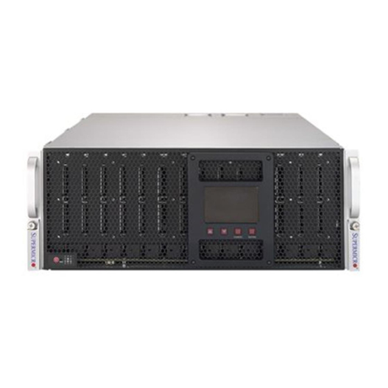
1-3 Server Chassis Features
Outlines the main features of the SC946TS-R2K05P chassis, such as system power, hard drives, and cooling.
1-4 Contacting Supermicro
Provides contact information for Supermicro headquarters, Europe, and Asia-Pacific offices.
Chapter 2: Server Installation
2-1 Overview
Provides a quick setup checklist for getting the 6048R-E1CR60N/L up and running.
2-2 Unpacking the System
Instructions for inspecting the system box and choosing a suitable location for the rack unit.
2-3 Preparing for Setup
Details on preparing for system setup, including checking included components and choosing a location.
2-4 Warnings and Precautions
Covers rack and server precautions, including ambient temperature, airflow, and electrical safety.
2-5 Rack Mounting Instructions
Step-by-step guide on installing the chassis into a rack unit using the provided rails.
Chapter 3: System Interface
3-1 Overview
Introduces the system interface, including the LCD screen and control panel features.
3-2 Control Panel Buttons
Explains the function of the power on/off and reset buttons on the chassis control panel.
3-3 Control Panel LEDs
Details the system status LEDs on the control panel and their meanings.
3-4 Drive Carrier LEDs
Describes the status LEDs on the SAS/SATA drive carriers, indicating drive presence and activity.
Chapter 4: Standardized Warning Statements
4-1 About Standardized Warning Statements
Introduction to industry-standard warnings provided to warn users of potential bodily injury.
Safety Warnings and Precautions
Collection of safety warnings in multiple languages regarding electrical hazards and procedures.
Installation Instructions
General instructions to read before connecting the system to the power source.
Circuit Breaker
Warning regarding building's short-circuit protection rating not exceeding 250V, 20A.
Power Disconnection Warning
Instruction to disconnect all power sources before accessing the chassis interior.
Equipment Installation
Warning that only trained and qualified personnel should install or service the equipment.
Battery Handling
Warning about explosion risk if battery is replaced incorrectly and proper disposal instructions.
Redundant Power Supplies
Caution that all power supply connections must be removed to de-energize the unit.
Backplane Voltage
Warning about hazardous voltage present on the backplane during operation.
Comply with Local and National Electrical Codes
Instruction to ensure equipment installation complies with local and national electrical codes.
Product Disposal
Guidance on handling product disposal according to national laws and regulations.
Hot Swap Fan Warning
Caution that fans may still be turning when removed; keep objects away from openings.
Power Cable and AC Adapter
Warning to use designated cables/adapters to prevent malfunction or fire.
Chapter 5: Advanced Serverboard Setup
5-1 Handling the Serverboard
Precautions for handling the serverboard to prevent damage from electrostatic discharge (ESD).
5-2 Connecting Cables
Instructions for connecting data, power, and control panel cables to the serverboard.
5-3 Rear I/O Ports
Details the colors and locations of the various I/O ports on the rear of the server.
5-4 Installing the Processor and Heatsink
Step-by-step guide for installing LGA2011 processors and their corresponding heatsinks.
5-5 Installing Memory
Instructions for installing DIMM modules into the memory slots for optimal performance.
5-6 Serverboard Details
Layout of the X10DSC+ serverboard, including jumper and connector locations.
X10DSC+ Quick Reference
A quick reference guide to jumpers, connectors, and LEDs on the X10DSC+ serverboard.
5-7 Connector Definitions
Detailed pin definitions for various power connectors, buttons, and headers on the serverboard.
5-8 Jumper Settings
Explanation of jumper functions for modifying serverboard operations and settings.
5-9 Onboard Indicators
Description of onboard indicators like IPMI LAN LEDs, BMC Heartbeat LED, and Power LEDs.
5-11 Installing Software
Guide for installing drivers and utilities from the Supermicro FTP site or website.
5-12 Onboard Battery
Instructions for installing the onboard battery and handling used batteries carefully.
Chapter 6: Advanced Chassis Setup
6-1 Static-Sensitive Devices
Precautions for handling static-sensitive devices to prevent damage to PCBs.
6-2 Control Panel
Details on connecting the control panel to the serverboard for system status indications.
6-3 Opening and Closing the Chassis Cover
Step-by-step instructions for safely opening and closing the server chassis cover.
6-4 System Fans
Information on the system's hot-swappable fans and procedures for replacing them.
6-5 Installing HDD Support Partitions
Guide for installing the necessary partitions before installing top-loading hard drives.
6-6 Installing 3.5" Hard Drives
Instructions for removing and installing 3.5" hot-swap hard drives using toolless carriers.
6-7 Installing 2.5" Drives
Guide for installing optional 2.5" hot-swappable hard drives in the rear of the chassis.
6-8 Installing NVMe Drives
Instructions for installing hot-swappable NVMe drives and their carriers into the NVMe drive cage.
6-9 Accessing Motherboard for Maintenance
Method for accessing the motherboard for memory upgrades and other maintenance tasks.
6-10 IPMI Connector
Procedure for accessing and connecting to the IPMI connector.
6-11 Accessing Backplane and Power Card
Steps for authorized personnel to access the backplane tray and power card.
6-12 Power Supply
Information on the redundant 1000W power supplies and how to change them.
Chapter 7: BIOS
7-1 Introduction
Describes the AMI BIOS setup utility for the X10DSC+, including basic navigation.
7-2 Main Setup
Details the items displayed in the Main BIOS setup screen and how to change system parameters.
7-3 Advanced Setup Configurations
Guides users through advanced BIOS settings, including boot features and power management.
CPU Configuration
Allows configuration of CPU settings, including frequency, cache, and core enablement.
Chipset Configuration
Settings for configuring the Intel North Bridge and IIO (Integrated I/O) options.
QPI Configuration
Settings for configuring Quick Path Interconnect (QPI) link speed and related features.
Memory RAS Configuration
Configuration options for Memory RAS settings like RAS Mode and Patrol Scrub.
South Bridge Configuration
Configuration options for South Bridge features, including USB and legacy device support.
SSATA Configuration
Settings for the onboard SATA controller, including drive type and hot-plug support.
7-4 Event Logs
Allows configuration of SMBIOS Event Log settings and viewing logged events.
7-5 IPMI
Configuration options for IPMI settings, including BMC network and system event logs.
7-6 Security Settings
Settings for system security, including password checks, administrator/user passwords, and secure boot.
7-7 Boot Settings
Allows configuration of system boot settings, including boot mode and device priorities.
7-8 Save & Exit
Options for saving configuration changes, discarding changes, and restoring defaults.
Appendix A: BIOS POST Error Codes
Motherboard BIOS Error Beep Codes
Lists motherboard BIOS error beep codes, their messages, and descriptions.
IPMI Error Codes
Lists IPMI error codes, including system overheat conditions.
Appendix B: System Specifications
Processors
Specifies supported processors: Single or dual Intel Xeon E5-2600 (v3) Series.
Chipset
Identifies the Intel C612 chipset used on the motherboard.
BIOS
Specifies the BIOS type: 16 Mb AMI SPI Flash ROM.
Memory Capacity
Details memory support: up to 1.5 TB LRDIMM or 768 GB RDIMM ECC DDR4.
Drive Bays
Describes drive bay configuration: 60x 3.5" hot-swap and 2x 2.5" hot-swap bays.
Expansion Slots
Indicates support for up to three PCI-E expansion cards.
Serverboard
Specifies the X10DSC+ serverboard (Extended ATX form factor) and its dimensions.
Chassis
Details the SC946TS-R2K05P chassis (4U rackmount) and its dimensions.
Need help?
Do you have a question about the 6048R-E1CR60L and is the answer not in the manual?
Questions and answers