Table of Contents
Advertisement
Quick Links
Advertisement
Table of Contents

Related Manuals for Supermicro SUPER 6047R-E1CR36N


Summary of Contents for Supermicro SUPER 6047R-E1CR36N
- Page 1 UPER ® UPER TORAGE YSTEM 6047R-E1CR36N USER’S MANUAL 1.0a...
- Page 2 This manual is written for professional system integrators and PC technicians. It mentation, is the property of Supermicro and/or its licensors, and is supplied only under a license. Any use or reproduction of this product is not allowed, except as expressly permitted by the terms provides information for the installation and use of the 6047R-E1CR36N.
- Page 3 Preface UPER TORAGE YSTEM 6047R-E1CR36N User's Manual Notes Chapter 5: Advanced Serverboard Setup Chapter 5 provides detailed information on the X9DRi-LN4F+ serverboard, includ- ing the locations and functions of connections, headers and jumpers. Refer to this chapter when adding or removing processors or main memory and when reconfig- uring the serverboard.
-
Page 4: Table Of Contents
Equipment Installation ..................4-8 Front Control Panel ..................1-3 Restricted Area ....................4-9 Cooling System ....................1-3 Battery Handling .................... 4-10 Contacting Supermicro ..................1-6 Redundant Power Supplies ................4-12 Chapter 2 Server Installation Backplane Voltage ..................4-13 Overview ......................2-1 Comply with Local and National Electrical Codes ........ - Page 5 UPER TORAGE YSTEM 6047R-E1CR36N User's Manual X9DRi-LN4F+ Quick Reference ..............5-16 Connector Definitions ................... 5-18 Jumper Settings .................... 5-25 5-10 Onboard Indicators ..................5-29 5-11 SATA Ports ....................5-30 5-12 Installing Software ..................5-31 SuperDoctor III ....................5-32 5-13 Onboard Battery .................... 5-34 Chapter 6 Advanced Chassis Setup Static-Sensitive Devices ..................
-
Page 6: Chapter 1 Introduction
SC847BE1C-R1K28LPB 4U/rack mount chassis and the X9DRi-LN4F+ dual processor serverboard. Please refer to our web site for information on operating systems that have been certified for use with the system (www.supermicro.com). In addition to the serverboard and chassis, various hardware components have been included with the 6047R-E1CR36N, as listed below: •... -
Page 7: Serverboard Features
(Socket R, LGA2011). Please refer to the serverboard description pages on a storage configuration. The following is a general outline of the main features of our web site for a complete listing of supported processors (www.supermicro.com). the chassis. Note: For E5-2600(v2) processor support, BIOS version 3.0 or above is required. - Page 8 Chapter 1: Introduction UPER TORAGE YSTEM 6047R-E1CR36N User's Manual Figure 1-1. Intel C600 Chipset: System Block Diagram Figure 1-2. X9DRi-LN4F+ Serverboard Note: This is a general block diagram. Please see Chapter 5 for details. FAN5 P2 DIMMG1 JPI2C1 JPW3 P2 DIMMG2 JPW2 JPW1 P1 DIMMA1...
-
Page 9: Contacting Supermicro
Super Micro Computer, Inc. 980 Rock Ave. San Jose, CA 95131 U.S.A. Tel: +1 (408) 503-8000 Fax: +1 (408) 503-8008 Email: marketing@supermicro.com (General Information) support@supermicro.com (Technical Support) Website: www.supermicro.com Europe Address: Super Micro Computer B.V. Het Sterrenbeeld 28, 5215 ML... -
Page 10: Chapter 2 Server Installation
Chapter 2: Server Installation Chapter 2 Server Installation Overview This chapter provides a quick setup checklist to get your SuperServer 6047R- E1CR36N up and running. Following these steps in the order given should enable you to have the system operational within a minimum amount of time. This quick setup assumes that your system has come to you with the processors and memory preinstalled. -
Page 11: Warnings And Precautions
Chapter 2: Server Installation UPER TORAGE YSTEM 6047R-E1CR36N User's Manual • Rack Mounting Considerations This product is for installation only in a Restricted Access Location (dedicated equipment rooms, service closets and the like). Ambient Operating Temperature • This product is not suitable for use with visual display work place devices If installed in a closed or multi-unit rack assembly, the ambient operating tempera- acccording to §2 of the the German Ordinance for Work with Visual Display Units. -
Page 12: Rack Mounting Instructions
Chapter 2: Server Installation UPER TORAGE YSTEM 6047R-E1CR36N User's Manual Rack Mounting Instructions 3. Secure the rail to the chassis with four screws as illustrated. This section provides information on installing the chassis into a rack unit with the 4. Repeat steps 1-3 for the other inner rack rail. rails provided. -
Page 13: Installing The Inner Rails On The Chassis
Chapter 2: Server Installation UPER TORAGE YSTEM 6047R-E1CR36N User's Manual Inner Rails L-min=676.00(26.61")(outer rail) 21D01 Figure 2-4. Extending and Releasing the Outer Rails Installing the Outer Rails on the Rack Installing the Outer Rails Figure 2-3. Installing the Inner Rails 1. - Page 14 UPER TORAGE YSTEM 6047R-E1CR36N User's Manual Figure 2-5. Installing into a Rack Notes: figures are for illustrative purposes only. Always install servers into racks from the bottom up. The chassis pictured may vary slightly from the 6047R- E1CR36N system chassis. Stability hazard.
-
Page 15: Chapter 3 System Interface
Chapter 3: System Interface Chapter 3 System Interface Overview There are several LEDs on the control panel as well as others on the drive carri- ers to keep you constantly informed of the overall status of the system as well as the activity and health of specific components. -
Page 16: Control Panel Leds
Chapter 3: System Interface UPER TORAGE YSTEM 6047R-E1CR36N User's Manual Control Panel LEDs The control panel located on the front of the chassis has several LEDs. These LEDs provide you with critical information related to different parts of the system. NIC2 This section explains what each LED indicates when illuminated and any corrective action you may need to take. - Page 17 UPER TORAGE YSTEM 6047R-E1CR36N User's Manual Notes...
-
Page 18: Chapter 4 Standardized Warning Statements For Ac Systems
Only certified technicians should attempt to install or configure components. Read this appendix in its entirety before installing or configuring components in the Supermicro chassis. These warnings may also be found on our web site at http://www.supermicro.com/ about/policies/safety_information.cfm. Warning Definition Warning! This warning symbol means danger. - Page 19 Warning Statements for AC Systems UPER TORAGE YSTEM 6047R-E1CR36N User's Manual Warnung جسذٌة اصابة ًتتسبب ف حالة ٌوكي أى ًاًك ف خطز ًٌٌع هذا الزهز !تحذٌز WICHTIGE SICHERHEITSHINWEISE الذوائز بالوخاطز الٌاجوة عي ي على علن ، ك هعذات تعول على أي قبل...
-
Page 20: Installation Instructions
Chapter 4: Warning Statements for AC Systems UPER TORAGE YSTEM 6047R-E1CR36N User's Manual Installation Instructions Circuit Breaker Warning! Warning! This product relies on the building's installation for short-circuit (overcurrent) Read the installation instructions before connecting the system to the power source. protection. -
Page 21: Power Disconnection Warning
Chapter 4: Warning Statements for AC Systems UPER TORAGE YSTEM 6047R-E1CR36N User's Manual ¡Advertencia! 경고! El sistema debe ser disconnected de todas las fuentes de energía y del cable 이 제품은 전원의 단락(과전류)방지에 대해서 전적으로 건물의 관련 설비에 eléctrico quitado de los módulos de fuente de alimentación antes de tener acceso 의존합니다. -
Page 22: Equipment Installation
Chapter 4: Warning Statements for AC Systems UPER TORAGE YSTEM 6047R-E1CR36N User's Manual Equipment Installation Waarschuwing Deze apparatuur mag alleen worden geïnstalleerd, vervangen of hersteld door Warning! geschoold en gekwalificeerd personeel. Only trained and qualified personnel should be allowed to install, replace, or service Restricted Area this equipment. -
Page 23: Battery Handling
Chapter 4: Warning Statements for AC Systems UPER TORAGE YSTEM 6047R-E1CR36N User's Manual Warnung אזור עם גישה מוגבלת Bei Einsetzen einer falschen Batterie besteht Explosionsgefahr. Ersetzen Sie die Batterie nur durch den gleichen oder vom Hersteller empfohlenen Batterietyp. !אזהרה Entsorgen Sie die benutzten Batterien nach den Anweisungen des Herstellers. יש... -
Page 24: Redundant Power Supplies
Chapter 4: Warning Statements for AC Systems UPER TORAGE YSTEM 6047R-E1CR36N User's Manual Redundant Power Supplies امداد الطاقة بوحدات عدة اتصاالت جهاز ال يكون لهذا قد الكهرباء عن وحدة ال لعسل كافة االتصاالت يجب إزالة 경고! Warning! This unit might have more than one power supply connection. All connections must 이... -
Page 25: Comply With Local And National Electrical Codes
Chapter 4: Warning Statements for AC Systems UPER TORAGE YSTEM 6047R-E1CR36N User's Manual Attention מתח בפנל האחורי L'équipement doit être installé conformément aux normes électriques nationales et locales. !הרה אז קיימת סכנת מתח בפנל האחורי בזמן תפעול המערכת. יש להיזהר במהלך תיאום... -
Page 26: Hot Swap Fan Warning
Chapter 4: Warning Statements for AC Systems UPER TORAGE YSTEM 6047R-E1CR36N User's Manual ¡Advertencia! 警告 當您從機架移除風扇裝置,風扇可能仍在轉動。小心不要將手指、螺絲起子和其他 Al deshacerse por completo de este producto debe seguir todas las leyes y 物品太靠近風扇。 reglamentos nacionales. Warnung Attention Die Lüfter drehen sich u. U. noch, wenn die Lüfterbaugruppe aus dem Chassis La mise au rebut ou le recyclage de ce produit sont généralement soumis à... -
Page 27: Power Cable And Ac Adapter
UL ou CSA câbles certifiés qui ont UL ou CSA indiqué sur le code power cables and AC adaptors. Using any other cables and adaptors could cause pour tous les autres appareils électriques que les produits désignés par Supermicro a malfunction or a fire. Electrical Appliance and Material Safety Law prohibits the seulement. - Page 28 UPER TORAGE YSTEM 6047R-E1CR36N User's Manual Notes 4-20...
-
Page 29: Chapter 5 Advanced Serverboard Setup
Chapter 5: Advanced Serverboard Setup Chapter 5 Advanced Serverboard Setup This chapter covers the steps required to install the X9DRi-LN4F+ serverboard into the chassis, connect the data and power cables and install add-on cards. All serverboard jumpers and connections are also described. A layout and quick refer- ence chart are included in this chapter for your reference. -
Page 30: Connecting Cables
UPER TORAGE YSTEM 6047R-E1CR36N User's Manual Chapter 5: Advanced Serverboard Setup Unpacking Figure 5-1. Control Panel Header Pins The serverboard is shipped in antistatic packaging to avoid electrical static dis- charge. When unpacking the board, make sure the person handling it is static Ground protected. -
Page 31: Installing The Processor And Heatsink
(Do not drop the • CPU on the socket. Do not move Refer to the Supermicro web site for updates on CPU support. the CPU horizontally or vertically and do not rub the CPU against Installing an LGA2011 Processor... -
Page 32: Installing A Passive Cpu Heatsink
UPER TORAGE YSTEM 6047R-E1CR36N User's Manual Chapter 5: Advanced Serverboard Setup Warning: You can only install the CPU to the socket in one direction. Make sure that Installing a Passive CPU Heatsink the CPU is properly inserted into the socket before closing the load plate. If it doesn't 1. -
Page 33: Removing The Heatsink
UPER TORAGE YSTEM 6047R-E1CR36N User's Manual Chapter 5: Advanced Serverboard Setup Installing Memory Removing the Heatsink Warning: We do not recommend that the CPU or the heatsink be removed. However, if you do need to uninstall the heatsink, please follow the instructions below to uninstall Warning: Exercise extreme care when installing or removing DIMM modules to prevent the heatsink to prevent damage done to the CPU or the CPU socket. - Page 34 CPU1/CPU Note: For detailed information on memory support and updates, please refer to the SMC Recommended 13 DIMMs~24 P1-DIMMA1/P1-DIMMB1, P2-DIMME1/P2-DIMMF1, P1-DIMMC1/P1-DIMMD1, P2-DIMMG1/ Memory List posted on our website at http://www.supermicro.com/support/resources/mem.cfm. DIMMs P2-DIMMH1, P1-DIMMA2/P1-DIMMB2, P2-DIMME2/P2-DIMMF2, P1-DIMMC2/P1-DIMMD2, P2-DIMMG2/P2-DIMMH2, P1-DIMMA3/P1-DIMMB3, P2-DIMME3/ Populating RDIMM (ECC) Memory Modules...
- Page 35 Capacity Channel (DPC) Note: For detailed information on memory support and updates, please refer to the SMC Recommended DIMM Per DIMM Memory List posted on our website at http://www.supermicro.com/support/resources/mem.cfm. 2 Slots Per Channel 3 Slots Per Channel & Data (See the Note...
-
Page 36: Adding Pci Add-On Cards
UPER TORAGE YSTEM 6047R-E1CR36N User's Manual Chapter 5: Advanced Serverboard Setup Adding PCI Add-On Cards Serverboard Details The 6047R-E1CR36N can accommodate up to three PCI-E x16 and one PCI-E x8 Figure 5-4. X9DRi-LN4F+ Layout low-profile expansion (add-on) cards. Installing an Add-on Card FAN5 P2 DIMMG1 JPI2C1... -
Page 37: X9Dri-Ln4F+ Quick Reference
UPER TORAGE YSTEM 6047R-E1CR36N User's Manual Chapter 5: Advanced Serverboard Setup X9DRi-LN4F+ Quick Reference (IPMI) LAN Dedicated IPMI LAN Onboard Buzzer (Internal Speaker) Jumper Description Default Setting USB 0/1 Back Panel USB 0/1 JBT1 Clear CMOS See Section 5-9 USB 2/3 Back Panel USB 2/3 C1/JI SMB to PCI-E Slots... -
Page 38: Connector Definitions
UPER TORAGE YSTEM 6047R-E1CR36N User's Manual Chapter 5: Advanced Serverboard Setup Connector Definitions Power Fail LED ATX Power 24-pin Connector Pin Definitions PWR Fail LED The Power Fail LED connection is Pin Definitions (JF1) Pin# Definition Pin # Definition located on pins 5 and 6 of JF1. Re- Power Connectors +3.3V +3.3V... - Page 39 UPER TORAGE YSTEM 6047R-E1CR36N User's Manual Chapter 5: Advanced Serverboard Setup Power On LED Chassis Intrusion Power LED Chassis Intrusion Pin Definitions (JF1) Pin Definitions The Power On LED connector is lo- The Chassis Intrusion header is des- Pin# Definition Pin# Definition cated on pins 15 and 16 of JF1 (use...
- Page 40 UPER TORAGE YSTEM 6047R-E1CR36N User's Manual Chapter 5: Advanced Serverboard Setup Serial Port Pin Definitions Serial Ports (COM1/COM2) IPMB Header IPMB Pin # Definition Pin # Definition Pin Definitions Two serial ports are included on the A System Management Bus header Pin# Definition serverboard.
-
Page 41: Jumper Settings
Note: UID can also be triggered via IPMI. For more information on IPMI, please refer to the IPMI User's Guide posted on our Website @http://www.supermicro.com. CMOS Clear JBT1 is used to clear CMOS (which will also clear any passwords). Instead of pins,... - Page 42 UPER TORAGE YSTEM 6047R-E1CR36N User's Manual Chapter 5: Advanced Serverboard Setup GLAN Enable/Disable Manufacturer's Mode GLAN Enable JPL1 enables or disables the GLAN Jumper Settings por ts on the ser verboard. See Jumper JPME2 allows the user to ME Mode Select Jumper Setting Definition Jumper Settings the table on the right for jumper...
-
Page 43: 5-10 Onboard Indicators
X8DT3/i-F/-LN4F UPER TORAGE YSTEM 6047R-E1CR36N User's Manual Chapter 5: Advanced Serverboard Setup X8DT3-LN4/LN4F 5-10 Onboard Indicators Watch Dog Enable/Disable Jumper JWD controls the Watch LAN LEDs Dog function. Watch Dog is a sys- The Ethernet ports (located beside the tem monitor that can reboot the JLAN1/2 LED VGA port) have two LEDs. -
Page 44: 5-11 Sata Ports
YSTEM 6047R-E1CR36N User's Manual Chapter 5: Advanced Serverboard Setup 5-11 SATA Ports 5-12 Installing Software The Supermicro FTP site contains drivers and utilities for your system at ftp://ftp. supermicro.com. Some of these must be installed, such as the chipset driver. Serial ATA Ports... -
Page 45: Superdoctor Iii
SuperDoctor III. Figure 5-6. SuperDoctor III Interface Display Screen (Health Information) Note: The SuperDoctor III program and User’s Manual can be downloaded from the Supermicro website at http://www.supermicro.com/products/accessories/soft- ware/SuperDoctorIII.cfm. For Linux, we recommend that you use the SuperDoctor II application instead. -
Page 46: 5-13 Onboard Battery
UPER TORAGE YSTEM 6047R-E1CR36N User's Manual 5-13 Onboard Battery Please handle used batteries carefully. Do not damage the battery in any way; a damaged battery may release hazardous materials into the environment. Do not discard a used battery in the garbage or a public landfill. Please comply with the regulations set up by your local hazardous waste management agency to dispose of your used battery properly. -
Page 47: Chapter 6 Advanced Chassis Setup
Chapter 6: Advanced Chassis Setup Chapter 6 Advanced Chassis Setup This chapter covers the steps required to install components and perform mainte- nance on the SC847BE1C-R1K28LPB chassis. For component installation, follow the steps in the order given to eliminate the most common problems encountered. If some steps are unnecessary, skip ahead to the step that follows. -
Page 48: Control Panel
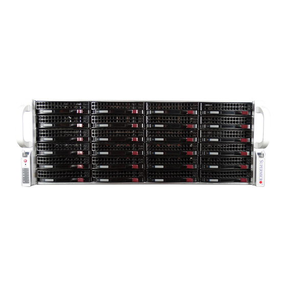
Chapter 6: Advanced Chassis Setup UPER TORAGE YSTEM 6047R-E1CR36N User's Manual Removing the Chassis Cover Figure 6-1. Front and Rear Chassis Views Control Panel Hard Drives (24) Power Supplies (2) I/O Ports Hardware RAID Add-on Card and JBOD Expansion Ports Figure 6-2. -
Page 49: System Fans
4. Replace the failed fan with an identical 8-cm, 12 volt fan (available from Note: You must use standard 1" high, drives in the SuperServer 6047R-E1CR36N. Supermicro). 5. Position the new fan into the space vacated by the failed fan previously re- Note: Use caution when working around the backplane. -
Page 50: Hard Drive Installation
5. Replace the drive tray into the chassis. Make sure to close the drive tray handle to lock the drive tray into place (see Figure 6-5).. Warning! Enterprise level hard disk drives are recommended for use in Supermicro chassis and servers. For information on recommended HDDs, visit the Supermicro website at http://www.supermicro.com/products/nfo/storage.cfm... -
Page 51: Removing The Air Shroud
Chapter 6: Advanced Chassis Setup UPER TORAGE YSTEM 6047R-E1CR36N User's Manual Installing Optional Fixed Hard Drives Removing the Air Shroud The SC847 chassis includes brackets for installing either one 3.5" fixed hard drive, Under most circumstances you will not need to remove the air shroud to perform or two 2.5"... -
Page 52: Power Supply
Replacements the power supply as follows: connect return bus to RTN connector, connect can be ordered directly from Supermicro (see contact information in the Preface). negative source voltage to -48V connector. Note: wires must be 10 AWG. The... - Page 53 UPER TORAGE YSTEM 6047R-E1CR36N User's Manual Figure 6-8. JBOD Expansion Port JBOD OUT (downstream ports) Note: the use of two cables (8x SAS lanes) is recommended. 6-12...
-
Page 54: Chapter 7 Bios
The configuration data that determines the system parameters may be changed by entering the AMI BIOS Setup utility. This Setup utility can be accessed by pressing <F2> at the appropriate time during system boot. Note: For AMI UEFI BIOS Recovery, please refer to the UEFI BIOS Recovery User Guide posted @http://www.supermicro.com/support/manuals/. -
Page 55: Main Setup
TORAGE YSTEM 6047R-E1CR36N User's Manual Starting the Setup Utility Supermicro X9DRi-LN4+ (Note: X9DR6-LN4+ images used for reference) Normally, the only visible Power-On Self-Test (POST) routine is the memory test. SMC Version As the memory is being tested, press the <F2> key to enter the main menu of This item displays the SMC version of the BIOS ROM used in this system. - Page 56 Chapter 7: BIOS UPER TORAGE YSTEM 6047R-E1CR36N User's Manual AddOn ROM Display Mode CPU Configuration Use this item to set the display mode for the Option ROM. Select Keep Current to This submenu displays the information of the CPU as detected by the BIOS. It also use the current AddOn ROM Display setting.
- Page 57 Chapter 7: BIOS UPER TORAGE YSTEM 6047R-E1CR36N User's Manual Clock Spread Spectrum based on the specifications of the application running in the system at the time. The options are Disabled and Enabled. Select Enable to enable Clock Spectrum support, which will allow the BIOS to moni- tor and attempt to reduce the level of Electromagnetic Interference caused by the Intel®...
- Page 58 Chapter 7: BIOS UPER TORAGE YSTEM 6047R-E1CR36N User's Manual Chipset Configuration CPU C3 Report Select Enabled to allow the BIOS to report the CPU C3 State (ACPI C2) to the operating system. During the CPU C3 State, the CPU clock generator is turned North Bridge Configuration off.
- Page 59 Chapter 7: BIOS UPER TORAGE YSTEM 6047R-E1CR36N User's Manual Port 1B Link Speed Up Tx Preset Select GEN1 to enable PCI-Exp Generation 1 support for Port 1B. Select GEN2 This feature allows the user to select the preset setting for a upstream component to enable PCI-Exp Generation 2 support for Port 1B.
- Page 60 Chapter 7: BIOS UPER TORAGE YSTEM 6047R-E1CR36N User's Manual Isoc Memory Mode Select Enabled to enable Ischronous support to meet QoS (Quality of Service) When Independent is selected, all DIMMs are available to the operating system. requirements. This feature is especially important for virtualization technology. When Mirroring is selected, the motherboard maintains two identical copies of all The options are Disabled and Enabled.
- Page 61 Chapter 7: BIOS UPER TORAGE YSTEM 6047R-E1CR36N User's Manual DRAM RAPL Legacy USB Support (Available when USB Functions is not Disabled) This item allows the user to select the average power limit setting when a DRAM Select Enabled to support legacy USB devices. Select Auto to disable legacy sup- module is in operation.
- Page 62 Chapter 7: BIOS UPER TORAGE YSTEM 6047R-E1CR36N User's Manual Aggressive Link Power Management Thermal Configuration Select Enabled to enable Aggressive Link Power Management support Thermal Management for Cougar Point B0 stepping and beyond. The options are Enabled and Select Enabled to initialize the PCH Thermal subsystem device located at D31:F6. Disabled.
- Page 63 Chapter 7: BIOS UPER TORAGE YSTEM 6047R-E1CR36N User's Manual PERR# Generation Option ROM is Enabled, and the default settings for LAN2 Option ROM~LAN4 Option ROM are Disabled. Select Enabled to allow a PCI device to generate a PERR number for a PCI Bus Signal Error Event.
- Page 64 Chapter 7: BIOS UPER TORAGE YSTEM 6047R-E1CR36N User's Manual VT-UTF8 Combo Key Support Console Redirection Settings Select Enabled to enable VT-UTF8 Combination Key support for ANSI/VT100 This feature allows the user to specify how the host computer will exchange terminals. The options are Enabled and Disabled. data with the client computer, which is the remote computer used by the user.
-
Page 65: Event Logs
Chapter 7: BIOS UPER TORAGE YSTEM 6047R-E1CR36N User's Manual TPM State TPM Support: Trusted Platform support Select Enabled to enable TPM security settings to improve data integrity and TPM State: Trusted Platform state network security. The options are Disabled and Enabled. Pending Operation: This item displays the status of a pending operation. - Page 66 Chapter 7: BIOS UPER TORAGE YSTEM 6047R-E1CR36N User's Manual Change SMBIOS Event Log Settings METW (Multiple Event Count Time Window) This item allows the user to decide how long (in minutes) should the multiple event This feature allows the user to configure SMBIOS Event settings. counter wait before generating a new event log.
-
Page 67: Ipmi
Chapter 7: BIOS UPER TORAGE YSTEM 6047R-E1CR36N User's Manual IPMI When SEL is Full This feature allows the user to decide what the BIOS should do when the system Use this feature to configure Intelligent Platform Management Interface (IPMI) event log is full. Select Erase Immediately to erase all events in the log when the settings. -
Page 68: Boot
Chapter 7: BIOS UPER TORAGE YSTEM 6047R-E1CR36N User's Manual Boot Security This submenu allows the user to configure the following boot settings for the This menu allows the user to configure the following security settings for the system. system. Administrator Password Boot Option Priorities Use this feature to set the Administrator Password which is required to enter the Boot Option #1... -
Page 69: Save & Exit
Chapter 7: BIOS UPER TORAGE YSTEM 6047R-E1CR36N User's Manual Save & Exit Discard Changes Select this feature and press <Enter> to discard all the changes and return to the This submenu allows the user to configure the Save and Exit settings for the BIOS setup. - Page 70 UPER TORAGE YSTEM 6047R-E1CR36N User's Manual Notes 7-32...
-
Page 71: Appendix A Bios Error Beep Codes
Appendix A: BIOS Error Beep Codes Appendix A BIOS Error Beep Codes During the POST (Power-On Self-Test) routines, which are performed at each system boot, errors may occur. Non-fatal errors are those which, in most cases, allow the system to continue to boot. - Page 72 UPER TORAGE YSTEM 6047R-E1CR36N User's Manual Notes...
-
Page 73: Appendix B System Specifications
Appendix B: System Specifications Appendix B System Specifications Processors Single or dual Intel® Xeon E5-2600 (v2) Series processors (Socket R, LGA2011) Notes: For E5-2600(v2) processor support, BIOS version 3.0 or above is required. Please refer to our web site for a complete listing of supported processors. Chipset Intel C600 chipset BIOS... - Page 74 Appendix B: System Specifications UPER TORAGE YSTEM 6047R-E1CR36N User's Manual Serverboard Regulatory Compliance X9DRi-LN4F+ (Extended ATX form factor) Electromagnetic Emissions: FCC Class A, EN 55022 Class A, EN 61000-3-2/-3-3, CISPR 22 Class A Dimensions: 13.68 x 13 in (347 x 330 mm) Electromagnetic Immunity: EN 55024/CISPR 24, (EN 61000-4-2, EN 61000-4-3, Chassis EN 61000-4-4, EN 61000-4-5, EN 61000-4-6, EN 61000-4-8, EN 61000-4-11)
- Page 75 YSTEM 6047R-E1CR36N User's Manual (continued from front) The products sold by Supermicro are not intended for and will not be used in life support systems, medical equipment, nuclear facilities or systems, aircraft, aircraft devices, aircraft/emergency com- munication devices or other critical systems whose failure to perform be reasonably expected to result in significant injury or loss of life or catastrophic property damage.
Need help?
Do you have a question about the SUPER 6047R-E1CR36N and is the answer not in the manual?
Questions and answers