Table of Contents
Advertisement
Quick Links
Проконсультироваться и купить данное оборудование вы можете в компании «АНД-Системс»
адрес: 125480, г.Москва, ул.Туристская, д.33/1; site: https://andpro.ru тел: +7 (495) 545-4870 email: info@andpro.ru
При обращении используйте промокод AND-PDF и получите скидку.
S
S
S
UPER
TORAGE
YSTEM
6038R-E1CR16H
USER'S MANUAL
1.0a
Advertisement
Table of Contents

Related Manuals for Supermicro 6038R-E1CR16H


Summary of Contents for Supermicro 6038R-E1CR16H
- Page 1 Проконсультироваться и купить данное оборудование вы можете в компании «АНД-Системс» адрес: 125480, г.Москва, ул.Туристская, д.33/1; site: https://andpro.ru тел: +7 (495) 545-4870 email: info@andpro.ru При обращении используйте промокод AND-PDF и получите скидку. UPER TORAGE YSTEM 6038R-E1CR16H USER’S MANUAL 1.0a...
- Page 2 This product, including software and docu- This manual is written for professional system integrators and PC technicians. It mentation, is the property of Supermicro and/or its licensors, and is supplied only under a license. provides information for the installation and use of the SuperStorageSystem 6038R- Any use or reproduction of this product is not allowed, except as expressly permitted by the terms of said license.
- Page 3 Preface UPER TORAGE YSTEM 6038R-E1CR16H User's Manual Notes chapter when adding or removing processors or main memory and when reconfig- uring the serverboard. Chapter 6: Advanced Chassis Setup Refer to Chapter 6 for detailed information on the SC836BE1C-R920B server chas- sis.
-
Page 4: Table Of Contents
Table of Contents UPER TORAGE YSTEM 6038R-E1CR16H User's Manual Table of Contents Control Panel Buttons ..................3-1 Reset ....................... 3-1 Power ......................3-1 Chapter 1 Introduction Control Panel LEDs ..................3-2 Overview ......................1-1 Information LED ....................3-2 Serverboard Features ..................1-2 Power ...................... - Page 5 Table of Contents UPER TORAGE YSTEM 6038R-E1CR16H User's Manual Memory Support ....................5-8 IPMI ....................... 7-42 DIMM Installation .................... 5-8 Security Settings ................... 7-44 Adding PCI Expansion Cards ................5-11 Boot Settings ....................7-45 Serverboard Details ..................5-12 Save & Exit ....................7-46 X10DRH-iT Quick Reference ................
-
Page 6: Super Storages System 6038R-E1Cr16H User's Manual
UPER TORAGE YSTEM 6038R-E1CR16H User's Manual Notes... -
Page 7: Chapter 1 Introduction
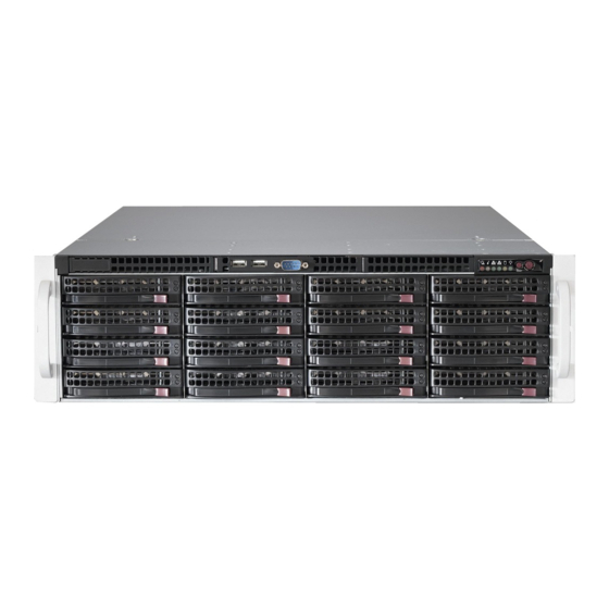
Chapter 1 Introduction Overview The SuperStorageSystem 6038R-E1CR16H is comprised of two main subsys- tems: the SC836BE1C-R920B 3U chassis and the X10DRH-iT dual processor serverboard. Please refer to our website for information on operating systems that have been certified for use with the system (www.supermicro.com). -
Page 8: Serverboard Features
Onboard Graphics Graphics are provided by an onboard ASpeed AST 2400 BMC, which supports IPMI. The SuperStorageSystem 6038R-E1CR16H is built around the X10DRH-iT, a dual processor serverboard based on the Intel C612 chipset. Below are the main features of the X10DRH-iT. (See Figure 1-1 for a block diagram of the chipset.) -
Page 9: Contacting Supermicro
Chapter 1: Introduction UPER TORAGE YSTEM 6038R-E1CR16H User's Manual Contacting Supermicro Headquarters Address: Super Micro Computer, Inc. Figure 1-1. Intel C612 Chipset: 980 Rock Ave. System Block Diagram San Jose, CA 95131 U.S.A. Tel: +1 (408) 503-8000 Note: This is a general block diagram. Please see Chapter 5 for details. - Page 10 UPER TORAGE YSTEM 6038R-E1CR16H User's Manual Notes...
-
Page 11: Chapter 2 Server Installation
Unpacking the System You should inspect the box the SuperServer 6038R-E1CR16H was shipped in and note if it was damaged in any way. If the server itself shows damage you should file a damage claim with the carrier who delivered it. -
Page 12: Warnings And Precautions
Chapter 2: Server Installation UPER TORAGE YSTEM 6038R-E1CR16H User's Manual Warnings and Precautions Rack Mounting Considerations Ambient Operating Temperature Rack Precautions • If installed in a closed or multi-unit rack assembly, the ambient operating tempera- Ensure that the leveling jacks on the bottom of the rack are fully extended to ture of the rack environment may be greater than the ambient temperature of the the floor with the full weight of the rack resting on them. -
Page 13: Installing The System Into A Rack
Chapter 2: Server Installation UPER TORAGE YSTEM 6038R-E1CR16H User's Manual Installing the Inner (Chassis) Rails Installing the System into a Rack Installing the Inner Rails This section provides information on installing the S836 chassis into a rack unit with the quick-release rails provided. There are a variety of rack units on the market, 1. -
Page 14: Installing The Outer (Rack) Rails
Chapter 2: Server Installation UPER TORAGE YSTEM 6038R-E1CR16H User's Manual Installing the Outer (Rack) Rails Installing the Sytem into a Rack Outer rails attach to the server rack and hold the server in place. The outer rails Installing into a Rack for the chassis extend between 30 inches and 33 inches. - Page 15 UPER TORAGE YSTEM 6038R-E1CR16H User's Manual Notes...
-
Page 16: Chapter 3 System Interface
Chapter 3: System Interface Chapter 3 System Interface Overview There are several LEDs on the control panel as well as others on the drive carriers, to keep you constantly informed of the overall status of the system, as well as the activity and health of specific components. -
Page 17: Control Panel Leds
Chapter 3: System Interface UPER TORAGE YSTEM 6038R-E1CR16H User's Manual Control Panel LEDs The control panel located on the front of the SC836 chassis has five LEDs. These LEDs provide you with critical information related to different parts of the system. -
Page 18: Drive Carrier Leds
UPER TORAGE YSTEM 6038R-E1CR16H User's Manual Drive Carrier LEDs The chassis includes externally accessible SAS/SATA drives. Each drive carrier displays two status LEDs on the front of the carrier. LED Color State Status Blue Solid On SAS/SATA drive installed Activity LED... -
Page 19: Chapter 4 Standardized Warning Statements For Ac Systems
Only certified technicians should attempt to install or configure components. Read this appendix in its entirety before installing or configuring components in the Supermicro chassis. These warnings may also be found on our web site at http://www.supermicro.com/ about/policies/safety_information.cfm. Warning Definition Warning! This warning symbol means danger. - Page 20 Warning Statements for AC Systems UPER TORAGE YSTEM 6038R-E1CR16H User's Manual Warnung جسذٌة اصابة ًتتسبب ف حالة ٌوكي أى ًاًك ف خطز ًٌٌع هذا الزهز !تحذٌز WICHTIGE SICHERHEITSHINWEISE الذوائز بالوخاطز الٌاجوة عي ي على علن ، ك هعذات تعول على أي...
-
Page 21: Installation Instructions
Chapter 4: Warning Statements for AC Systems UPER TORAGE YSTEM 6038R-E1CR16H User's Manual Installation Instructions Circuit Breaker Warning! Warning! This product relies on the building's installation for short-circuit (overcurrent) Read the installation instructions before connecting the system to the power source. -
Page 22: Power Disconnection Warning
Chapter 4: Warning Statements for AC Systems UPER TORAGE YSTEM 6038R-E1CR16H User's Manual ¡Advertencia! 경고! El sistema debe ser disconnected de todas las fuentes de energía y del cable 이 제품은 전원의 단락(과전류)방지에 대해서 전적으로 건물의 관련 설비에 eléctrico quitado de los módulos de fuente de alimentación antes de tener acceso 의존합니다. -
Page 23: Equipment Installation
Chapter 4: Warning Statements for AC Systems UPER TORAGE YSTEM 6038R-E1CR16H User's Manual Equipment Installation Waarschuwing Deze apparatuur mag alleen worden geïnstalleerd, vervangen of hersteld door Warning! geschoold en gekwalificeerd personeel. Only trained and qualified personnel should be allowed to install, replace, or service Restricted Area this equipment. -
Page 24: Battery Handling
Chapter 4: Warning Statements for AC Systems UPER TORAGE YSTEM 6038R-E1CR16H User's Manual Warnung אזור עם גישה מוגבלת Bei Einsetzen einer falschen Batterie besteht Explosionsgefahr. Ersetzen Sie die Batterie nur durch den gleichen oder vom Hersteller empfohlenen Batterietyp. !אזהרה Entsorgen Sie die benutzten Batterien nach den Anweisungen des Herstellers. -
Page 25: Redundant Power Supplies
Chapter 4: Warning Statements for AC Systems UPER TORAGE YSTEM 6038R-E1CR16H User's Manual Redundant Power Supplies امداد الطاقة بوحدات عدة اتصاالت جهاز ال يكون لهذا قد الكهرباء عن وحدة ال لعسل كافة االتصاالت يجب إزالة 경고! Warning! This unit might have more than one power supply connection. All connections must 이... -
Page 26: Comply With Local And National Electrical Codes
Chapter 4: Warning Statements for AC Systems UPER TORAGE YSTEM 6038R-E1CR16H User's Manual Attention מתח בפנל האחורי L'équipement doit être installé conformément aux normes électriques nationales et locales. !הרה אז קיימת סכנת מתח בפנל האחורי בזמן תפעול המערכת. יש להיזהר במהלך... -
Page 27: Hot Swap Fan Warning
Chapter 4: Warning Statements for AC Systems UPER TORAGE YSTEM 6038R-E1CR16H User's Manual ¡Advertencia! 警告 當您從機架移除風扇裝置,風扇可能仍在轉動。小心不要將手指、螺絲起子和其他 Al deshacerse por completo de este producto debe seguir todas las leyes y 物品太靠近風扇。 reglamentos nacionales. Warnung Attention Die Lüfter drehen sich u. U. noch, wenn die Lüfterbaugruppe aus dem Chassis La mise au rebut ou le recyclage de ce produit sont généralement soumis à... -
Page 28: Power Cable And Ac Adapter
UL ou CSA câbles certifiés qui ont UL ou CSA indiqué sur le code power cables and AC adaptors. Using any other cables and adaptors could cause pour tous les autres appareils électriques que les produits désignés par Supermicro a malfunction or a fire. Electrical Appliance and Material Safety Law prohibits the seulement. - Page 29 UPER TORAGE YSTEM 6038R-E1CR16H User's Manual Notes 4-20...
-
Page 30: Chapter 5 Advanced Serverboard Setup
Chapter 5: Advanced Serverboard Setup Chapter 5 Advanced Serverboard Setup This chapter is provided as a reference and describes the data and power cable connections and add-on cards. All serverboard jumpers and connections are also described. A layout and quick reference chart are included in this chapter for your reference. -
Page 31: Connecting Cables
Chapter 5: Advanced Serverboard Setup UPER TORAGE YSTEM 6038R-E1CR16H User's Manual Connecting Cables Figure 5-1. Control Panel Header Pins Several cables need to be connected to the serverboard. These include the data cables for the peripherals and control panel and the power cables. -
Page 32: Installing The Processor And Heatsink
(Do not drop the • CPU on the socket. Do not move Refer to the Supermicro web site for updates on CPU support. the CPU horizontally or vertically and do not rub the CPU against Installing an LGA2011 Processor... -
Page 33: Installing A Passive Cpu Heatsink
Chapter 5: Advanced Serverboard Setup UPER TORAGE YSTEM 6038R-E1CR16H User's Manual Installing a Passive CPU Heatsink Warning: You can only install the CPU to the socket in one direction. Make sure that the CPU is properly inserted into the socket before closing the load plate. If it doesn't 1. -
Page 34: Installing Memory
Chapter 5: Advanced Serverboard Setup UPER TORAGE YSTEM 6038R-E1CR16H User's Manual Installing Memory Processor & Memory Module Population Configuration For the memory to work properly, follow the tables below for correct installation. Caution: Exercise extreme care when installing or removing DIMM modules to prevent Processors and their Corresponding Memory Modules any possible damage. -
Page 35: Adding Pci Expansion Cards
LICENSE LICENSE The 6038R-E1CR16H can accommodate up to five PCI expansion cards in the PCI expansion slots on the serverboard. Note that two of the slots are already populated with the Hardware RAID controller card and the JBOD expansion card. -
Page 36: Serverboard Details
Blue: On Unit Identified on the X10DRH-iT. Onboard PWR LED Power On The 6038R-E1CR16H comes pre-installed with a Hardware RAID controller installed LEDM1 BMC Heartbeat LED Green: Blinking BMC Normal in PCI-E slot 2 and a JBOD expansion port installed in PCI-E slot 1. -
Page 37: Connector Definitions
Chapter 5: Advanced Serverboard Setup UPER TORAGE YSTEM 6038R-E1CR16H User's Manual Connector Definitions Power Fail LED ATX Power 24-pin Connector PWR Fail LED Pin Definitions Pin Definitions (JF1) The Power Fail LED connection is Pin# Definition Pin # Definition Pin# Definition located on pins 5 and 6 of JF1. - Page 38 Chapter 5: Advanced Serverboard Setup UPER TORAGE YSTEM 6038R-E1CR16H User's Manual Power On LED Power LED Internal Speaker Internal Buzzer (SP1) Pin Definitions (JF1) The Power On LED connector is lo- Pin Definition The internal speaker, located at SP1, Pin#...
- Page 39 Note: UID can also be triggered via IPMI. For more information on IPMI, please to use the IPMB I C connection on Clock refer to the IPMI User's Guide posted on our website at http://www.supermicro.com. your system. No Connection 5-18...
-
Page 40: Jumper Settings
Chapter 5: Advanced Serverboard Setup UPER TORAGE YSTEM 6038R-E1CR16H User's Manual Jumper Settings TPM/Port 80 Header Pin Definitions Pin # Definition Pin # Definition Explanation of Jumpers TPM Header/Port 80 LCLK A Trusted Platform Module/Port 80 To modify the operation of the LFRAME# <(KEY)>... - Page 41 Chapter 5: Advanced Serverboard Setup UPER TORAGE YSTEM 6038R-E1CR16H User's Manual Watch Dog Enable/Disable LAN Enable/Disable GLAN Enable Jumper Settings JPL1 enables or disables the Gb LAN Jumper JWD1 controls the Watch Jumper Setting Definition ports on the serverboard. See the Dog function.
-
Page 42: 5-10 Onboard Indicators
3.0/SAS 3.0 hard drives. ated with the connection speed LED. Note: For more information on SATA HostRAID configuration, please refer to the Intel SATA HostRAID User's Guide posted on our website at http://www.supermicro. com.. Dedicated IPMI LAN LEDs IPMI LAN Link LED (Left) &... -
Page 43: 5-12 Installing Software
YSTEM 6038R-E1CR16H User's Manual 5-12 Installing Software SuperDoctor® 5 The Supermicro SuperDoctor 5 is a program that functions in a command-line or The Supermicro FTP site contains drivers and utilities for your system at ftp://ftp. web-based interface in Windows and Linux operating systems. The program moni- supermicro.com. -
Page 44: 5-13 Onboard Battery
UPER TORAGE YSTEM 6038R-E1CR16H User's Manual 5-13 Onboard Battery Care must be taken to assure that the chassis cover is in place when the system is operating to assure proper cooling. Out of warranty damage to the system can occur if this practice is not strictly followed. -
Page 45: Chapter 6 Advanced Chassis Setup
Chapter 6: Advanced Chassis Setup Chapter 6 Advanced Chassis Setup This chapter covers the steps required to install components and perform mainte- nance on the SC836BE1C-R920B chassis. For component installation, follow the steps in the order given to eliminate the most common problems encountered. If some steps are unnecessary, skip ahead to the step that follows. -
Page 46: Control Panel
Chapter 6: Advanced Chassis Setup UPER TORAGE YSTEM 6038R-E1CR16H User's Manual Figure 6-1. Front and Rear Chassis Views Control Panel SAS/SATA Drives (16) Note: numbers indicate the logical drive bay locations/. Power Supplies 7 PCI Expansion Slots JBOD Expansion Ports... -
Page 47: Replacing System Fans
Chapter 6: Advanced Chassis Setup UPER TORAGE YSTEM 6038R-E1CR16H User's Manual Replacing System Fans 1. Open the chassis and locate the faulty fan. Never run the server for an ex- tended period of time with the chassis open. 2. Press the release tab on the fan and pull the fan upward. -
Page 48: Drive Bay Installation/Removal
Note: Refer to the following ftp site for setup guidelines: <ftp://ftp.supermicro.com/ driver/SAS/LSI/LSI_SAS_EmbMRAID_SWUG.pdf> and Supermicro's web site for additional inmformation < http://www.supermicro.com/support/manuals/>. Warning! Enterprise level hard disk drives are recommended for use in Supermicro chassis and servers. For information on recommended HDDs, visit the Supermicro Handle website at http://www.supermicro.com/products/nfo/files/storage/SAS-1-Com-... -
Page 49: Hard Drive Backplane
Power Supply Figure 6-6. Mounting a Drive in a Carrier The 6038R-E1CR16H has a 920 watt redundant power supply consisting of two hot- plug power modules. Each power supply module has an auto-switching capability, which enables it to automatically sense and operate at a 100V - 240V input voltage. -
Page 50: Replacing The Power Distributor
1. Power-down the server and remove the cord from the wall socket or power strip. The 6038R-E1CR16H features dual JBOD expansion ports. The figure below il- lustrates the recommended expansion strategy. The JBOD attachment will vary 2. Remove all cable connections from the power supply to the motherboard, depending on the specific JBOD chassis that is being connected. - Page 51 UPER TORAGE YSTEM 6038R-E1CR16H User's Manual Figure 6-9. JBOD Expansion JBOD OUT (downstream ports) Note: the use of two cables (8x SAS lanes) is recommended. 6-12...
-
Page 52: Chapter 7 Bios
When an option is selected in the left frame, it is highlighted in white. Often a text message will accompany it. Note: the AMI BIOS has default text messages built in. Supermicro retains the option to include, omit, or change any of these text messages. -
Page 53: How To Start The Setup Utility
Flashing the wrong BIOS can cause irreparable damage to the system. In no event shall as 17:30:00. Supermicro be liable for direct, indirect, special, incidental, or consequential damages arising from a BIOS update. If you have to update the BIOS, do not shut down or reset Supermicro X10DRH-C/i the system while the BIOS is updating to avoid possible boot failure. -
Page 54: Advanced Setup Configurations
UPER TORAGE YSTEM 6038R-E1CR16H User's Manual Chapter 7: BIOS Advanced Setup Configurations Wait For 'F1' If Error Select Enabled to force the system to wait until the <F1> key is pressed if an error Use the arrow keys to select Advanced setup and press <Enter> to access the occurs. - Page 55 UPER TORAGE YSTEM 6038R-E1CR16H User's Manual Chapter 7: BIOS CPU Configuration illegal codes to overwhelm the processor to damage the system during an attack. The options are Enable and Disable. (Refer to Intel's and Microsoft's websites for This submenu displays the following CPU information as detected by the BIOS. It more information.)
- Page 56 UPER TORAGE YSTEM 6038R-E1CR16H User's Manual Chapter 7: BIOS AES-NI CPU C State Control (Available when Power Technology is set to Custom) Select Enable to use the Intel Advanced Encryption Standard (AES) New Instruc- tions (NI) to ensure data security. The options are Enable and Disable.
- Page 57 UPER TORAGE YSTEM 6038R-E1CR16H User's Manual Chapter 7: BIOS Long Pwr (Power) Limit Ovrd (Override) Override BW_LIMIT_TF (BW_limit_tf ) Select Enable to support long-term power limit override. If this feature is disabled, This feature allows the user to turn off the "Override BW_Limit_TF (Time Frame)"...
- Page 58 UPER TORAGE YSTEM 6038R-E1CR16H User's Manual Chapter 7: BIOS No PCIe Port Active ECO (Engineer Change Order) L0s Support This feature provides a work-around solution when there is no active PCI device When this item is set to Disable, IIO will not put its transmitter in the L0s state.
- Page 59 UPER TORAGE YSTEM 6038R-E1CR16H User's Manual Chapter 7: BIOS PCI-E Port L1 Exit Latency dB), P5 (0.0/2.0 dB), P6 (0.0/2.5 dB), P7 (-6.0 /3.5 dB), P8 (-3.5/3.5 dB), and P9 (0.0/3.5 dB). Use this item to set the length of time required for the port specified by the user to complete the transition from L1 to L0.
- Page 60 UPER TORAGE YSTEM 6038R-E1CR16H User's Manual Chapter 7: BIOS No PCIe Port Active ECO (Engineer Change Order) PCI-E Port L1 Exit Latency This feature provides a work-around solution when there is no active PCI device Use this item to set the length of time required for the port specified by the user detected by the BIOS.
- Page 61 UPER TORAGE YSTEM 6038R-E1CR16H User's Manual Chapter 7: BIOS dB), P5 (0.0/2.0 dB), P6 (0.0/2.5 dB), P7 (-6.0 /3.5 dB), P8 (-3.5/3.5 dB), and Intel VT for Directed I/O (VT-d) P9 (0.0/3.5 dB). Intel VT for Directed I/O (VT-d) ®...
-
Page 62: Memory Configuration
UPER TORAGE YSTEM 6038R-E1CR16H User's Manual Chapter 7: BIOS Link L1 Enable Set Throttling Mode Select Enable for Link L1 support to reduce power consumption. The options Throttling improves CPU reliability and reduces power consumption via automat- are Enable and Disable. -
Page 63: Usb Configuration
UPER TORAGE YSTEM 6038R-E1CR16H User's Manual Chapter 7: BIOS Patrol Scrub Interval Port 60/64 Emulation This feature allows you to decide how many hours the system should wait before Select Enabled to support I/O port 60h/64h emulation, which will provide complete the next complete patrol scrub is performed. - Page 64 UPER TORAGE YSTEM 6038R-E1CR16H User's Manual Chapter 7: BIOS SATA Configuration *If the item above "Configure SATA as" is set to IDE, the following items will display: When this submenu is selected, AMI BIOS automatically detects the presence of...
- Page 65 UPER TORAGE YSTEM 6038R-E1CR16H User's Manual Chapter 7: BIOS sSATA Port 0~ Port 3 Port 0~ Port 5 Select Enabled to enable a SATA port specified by the user. The options are Select Enabled to enable an sSATA port specified by the user. The options are Disabled and Enabled.
- Page 66 UPER TORAGE YSTEM 6038R-E1CR16H User's Manual Chapter 7: BIOS PCIe/PCI/PnP Configuration sSATA Port 0~ Port 3 Select Enabled to enable an sSATA port specified by the user. The options are PCI Latency Timer Disabled and Enabled. Use this item to configure the PCI latency timer for a device installed on a PCI bus.
- Page 67 UPER TORAGE YSTEM 6038R-E1CR16H User's Manual Chapter 7: BIOS Super IO Configuration MMIOHBase Use this item to select the I/O base memory size according to memory-address Super IO Chip AST2400 mapping for the PCH chip. The base memory size must be between 4032G to ...
- Page 68 UPER TORAGE YSTEM 6038R-E1CR16H User's Manual Chapter 7: BIOS VT-UTF8 Combo Key Support *If the item above set to Enabled, the following items will become available for configuration: Select Enabled to enable VT-UTF8 Combination Key support for ANSI/VT100 terminals. The options are Enabled and Disabled.
- Page 69 UPER TORAGE YSTEM 6038R-E1CR16H User's Manual Chapter 7: BIOS SOL/COM2 Console Redirection Settings VT-UTF8 Combo Key Support Select Enabled to enable VT-UTF8 Combination Key support for ANSI/VT100 Use this feature to specify how the host computer will exchange data with the client terminals.
- Page 70 UPER TORAGE YSTEM 6038R-E1CR16H User's Manual Chapter 7: BIOS The following settings will be displayed: Serial Port for Out-of-Band Management/Windows Emergency Management Services (EMS) Data Bits, Parity, Stop Bits The submenu allows the user to configure Console Redirection settings to support Out-of-Band Serial Port management.
-
Page 71: Iscsi Configuration
UPER TORAGE YSTEM 6038R-E1CR16H User's Manual Chapter 7: BIOS ACPI Settings 6. From the window that pops up, select "Enabled" and press <Enter>. WHEA Support Select Enabled to support the Windows Hardware Error Architecture (WHEA) plat- form and provide a common infrastructure for the system to handle hardware errors within the Windows OS environment to reduce system crashes and to enhance system recovery and health monitoring. -
Page 72: Event Logs
UPER TORAGE YSTEM 6038R-E1CR16H User's Manual Chapter 7: BIOS Event Logs When Log is Full Select Erase Immediately to immediately erase all errors in the SMBIOS event log This submenu allows the user to configure Event Log settings. when the event log is full. Select Do Nothing for the system to do nothing when the SMBIOS event log is full. - Page 73 UPER TORAGE YSTEM 6038R-E1CR16H User's Manual Chapter 7: BIOS IPMI BMC Network Configuration The following items will be displayed: This submenu allows the user to configure Intelligent Platform Management Inter- • IPMI LAN Selection face (IPMI) settings. • IPMI Network Link Status...
- Page 74 UPER TORAGE YSTEM 6038R-E1CR16H User's Manual Chapter 7: BIOS Security Settings Boot Settings This submenu allows the user to configure the following security settings for the This submenu allows the user to configure Boot settings for this system: system. Boot Configuration...
-
Page 75: Save & Exit
UPER TORAGE YSTEM 6038R-E1CR16H User's Manual Chapter 7: BIOS Delete Boot Option Discard Changes and Exit Select the target boot device to delete from the boot priority list. Select this item to exit from the BIOS setup without making any permanent changes to the system configuration, and reboot the computer. - Page 76 UPER TORAGE YSTEM 6038R-E1CR16H User's Manual Notes 7-48...
- Page 77 Appendix A: BIOS POST Error Codes Appendix A BIOS POST Error Codes During the POST (Power-On Self-Test) routines, which are performed upon each system boot, errors may occur. Non-fatal errors are those which, in most cases, allow the system to continue to boot.
- Page 78 UPER TORAGE YSTEM 6038R-E1CR16H User's Manual Notes...
-
Page 79: System Specifications
Appendix B: System Specifications Appendix B System Specifications Processors Single or dual Intel® Xeon E5-2600 (v3/v4) Series processors Note: Please refer to our web site for a complete listing of supported processors. Chipset Intel C612 chipset BIOS 128 Mb AMI® SPI Flash ROM Memory Capacity Sixteen DIMM sockets supporting up to 2 TB of Load Reduced (LRDIMM) or 1 TB of Registered (RDIMM) ECC DDR4-2400/2133/1866/1600 memory... - Page 80 (continued from front) Canada), CE Marking (Europe) The products sold by Supermicro are not intended for and will not be used in life support systems, medical equipment, nuclear facilities or systems, aircraft, aircraft devices, aircraft/emergency com- California Best Management Practices Regulations for Perchlorate Materials:...
- Page 81 UPER TORAGE YSTEM 6038R-E1CR16L User's Manual Notes...
Need help?
Do you have a question about the 6038R-E1CR16H and is the answer not in the manual?
Questions and answers