Table of Contents
Advertisement
SERVICE MANUAL
The SA-VE702 system consists of one unit
of SA-WMS5 and two units of SS-MS7.
The SA-VE705 system consists of one unit
of SA-WMS7 and five units of SS-MS7.
AUDIO POWER SPECIFICATIONS:
US model
POWER OUTPUT AND TOTAL
HARMONIC DISTORTION :
with 8 Ω loads, both channels driven, from 20 - 150Hz; rates
120 W per channel minimum RMS power, with no more
than 0.8% total harmonic distortion from 250 mW to rated
output.
SS-MS7 (
front, center, and rear speakers)
Speaker system
2 way, magnetically shielded
Speaker units
3
/
Tweeter :
1.9 cm (
4
2
Woofer :
5 cm (
in.)
type
Enclosure type
Bass reflex
8 Ω
Rated impedance
Power handling capacity
Maximum input power: 140 W
Sensitivity level
87 dB (1W, 1m)
Frequency range
120 Hz - 40,000 Hz
Dimensions (w/h/d)
When attached speaker grilles:
Approx. 86 × 169 × 130 mm
/2 × 6
/4 × 5
(3
1
3
When attached to supplied speaker stand:
Approx. 96 × 207 × 141 mm
/8 × 8
/4 × 5
7
1
(3
(Front (and rear)speakers)
Approx. 169 × 131 × 144 mm
/4 × 5
/4 × 5
3
1
(6
(Center speaker: pointed upwards)
Approx. 169 × 118 × 141 mm
/4 × 4
/4 × 5
(6
3
3
(Center speaker: pointed
downwards):
MICROFILM
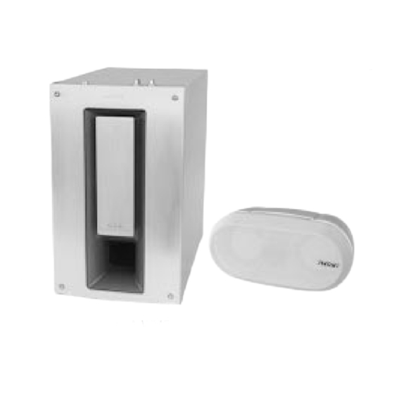
Photo : SA-WMS7
SPECIFICATIONS
Mass
When attached speaker grilles:
When attached to supplied speaker stand:
SS-WMS7 (subwoofer)
System
Speaker system
in.), dome type
Speaker unit
× 2
, balanced drive
Enclosure type
Practical maximum output
Reproduction frequency range
Inputs
LINE IN (input pin jack)
SPEAKER IN (input terminals)
Outputs
LINE OUT (output pin jack)
1
/8 in.) each
SPEAKER OUT (output terminals)
General
Power requirements
5
USA and Canada :
/8 in.) each
Europe :
Others :
3
Power consumptions
/4 in.),
Dimensions (w/h/d)
5
/8 in.),
Mass
SA-VE702/VE705/
WMS7/SS-MS7
Photo : SS-MS7
Supplied accessories
SA-VE705
Approx. 1.3 kg (2lb 14oz) each
Speaker stands (for the front and rear speakers) (4)
Speaker stand (for the center speaker) (1)
Approx. 1.4 kg (3lb 1oz) each,
Screws (for the speaker stands) (10)
(Front (and rear) speakers)
Washers (for the speaker stands) (10)
Approx. 1.4 kg (3lb 1oz)(Center
Brackets (for the front and rear speaker stands) (4)
speaker)
Speaker grilles (5)
Audio connecting cord (1)
Speaker connecting cords, 2.5 m(8 ft
Active subwoofer, magnetically
Speaker connecting cords, 10 m(32 ft
shielded
Woofer : 20 cm (8 in.),
SA-VE702
cone type
Speaker stands (for the front speakers) (2)
Advanded SAW type
Screws (for the speaker stands) (4)
Washers (for the speaker stands) (4)
120 W
Brackets (for the front speaker stands) (2)
Speaker grilles (2)
24 Hz - 150 Hz
Audio connecting cord (1)
Speaker connecting cords, 2.5 m(8 ft
Design and specifications are subject to change
without notice
120 V AC, 60 Hz
220 - 230 V AC, 50/60 Hz
220 - 240 V AC, 50/60 Hz
80 W
Approx. 230 × 380 × 470 mm
/8 × 15 × 18
1
5
(9
/8 in.), including
front grille
Approx. 17 kg
(37 lb 8oz)
MICRO SATELLITE SYSTEM
US Model
Canadian Model
SA-VE705/WMS7/SS-MS7
AEP Model
UK Model
E Model
2
1
/
in.) (5)
2
3
9
/
in.) (2)
4
1
2
/
in.) (4)
2
Advertisement
Table of Contents

Related Manuals for Sony SA-VE705


Summarization of Contents
SPECIFICATIONS
AUDIO POWER SPECIFICATIONS
Details on US model power output and total harmonic distortion.
SPEAKER AND SUBWOOFER SPECIFICATIONS
Technical specifications for SS-MS7 speakers and SS-WMS7 subwoofer.
SUPPLIED ACCESSORIES
List of accessories included with SA-VE705 and SA-VE702 systems.
SAFETY CHECK-OUT
AC LEAKAGE TESTING
Procedures and methods for checking AC leakage on exposed metal parts.
SAFETY-RELATED COMPONENT WARNING
CRITICAL SAFETY COMPONENTS
Identifies components critical to safe operation, marked with ▲.
GENERAL INFORMATION
LOCATION OF CONTROLS (SA-WMS7)
Identifies controls on the front and rear of the SA-WMS7 unit.
DIAGRAM INFORMATION
NOTES AND LOCATIONS
Explains diagram conventions and identifies circuit board locations.
SCHEMATIC DIAGRAMS
Provides detailed circuit schematics for various boards of the system.
PRINTED WIRING BOARD DIAGRAMS
Shows printed wiring board layouts for main and power sections.
CONTROL SECTION WIRING DIAGRAMS
Details printed wiring boards for control, auto power, and LED sections.
IC BLOCK DIAGRAMS
Illustrates the functional blocks of key integrated circuits used in the system.
EXPLODED VIEWS
FRONT PANEL SECTION (SA-WMS7)
Exploded view and parts list for the front panel assembly of SA-WMS7.
AMPLIFIER SECTION (SA-WMS7)
Exploded view and parts list for the amplifier section of SA-WMS7.
SS-MS7 SPEAKER ASSEMBLY
Exploded view and parts list for the SS-MS7 speaker assembly.
ELECTRICAL PARTS LIST
AUTO POWER BOARD COMPONENTS
Lists capacitors, transistors, resistors, and other parts for the auto power board.
CONTROL AND LED BOARD COMPONENTS
Lists parts for control and LED boards, including capacitors, ICs, and resistors.
MAIN BOARD COMPONENTS
Lists connectors, diodes, fuses, ICs, resistors, relays, and terminals for the main board.
POWER SWITCH BOARD COMPONENTS
Lists capacitors, connectors, transistors, resistors, and switches for the power switch board.
ACCESSORIES AND PACKING MATERIALS
Lists cables, manuals, and packing materials supplied with the system.
HARDWARE LIST
Lists screws, nuts, and other hardware used in the assembly.
Need help?
Do you have a question about the SA-VE705 and is the answer not in the manual?
Questions and answers