Table of Contents
Advertisement
SERVICE MANUAL
The SA-VE702 system consists of one unit
of SA-WMS5 and two units of SS-MS7.
The SA-VE705 system consists of one unit
of SA-WMS7 and five units of SS-MS7.
AUDIO POWER SPECIFICATIONS:
US model
POWER OUTPUT AND TOTAL
HARMONIC DISTORTION :
with 8 Ω loads, both channels driven, from 20 - 150Hz; rates
120 W per channel minimum RMS power, with no more
than 0.8% total harmonic distortion from 250 mW to rated
output.
SS-MS7 (
front, center, and rear speakers)
Speaker system
2 way, magnetically shielded
Speaker units
3
/
Tweeter :
1.9 cm (
4
2
Woofer :
5 cm (
in.)
type
Enclosure type
Bass reflex
8 Ω
Rated impedance
Power handling capacity
Maximum input power: 140 W
Sensitivity level
87 dB (1W, 1m)
Frequency range
120 Hz - 40,000 Hz
Dimensions (w/h/d)
When attached speaker grilles:
Approx. 86 × 169 × 130 mm
/2 × 6
/4 × 5
(3
1
3
When attached to supplied speaker stand:
Approx. 96 × 207 × 141 mm
/8 × 8
/4 × 5
7
1
(3
(Front (and rear)speakers)
Approx. 169 × 131 × 144 mm
/4 × 5
/4 × 5
3
1
(6
(Center speaker: pointed upwards)
Approx. 169 × 118 × 141 mm
/4 × 4
/4 × 5
(6
3
3
(Center speaker: pointed
downwards):
MICROFILM
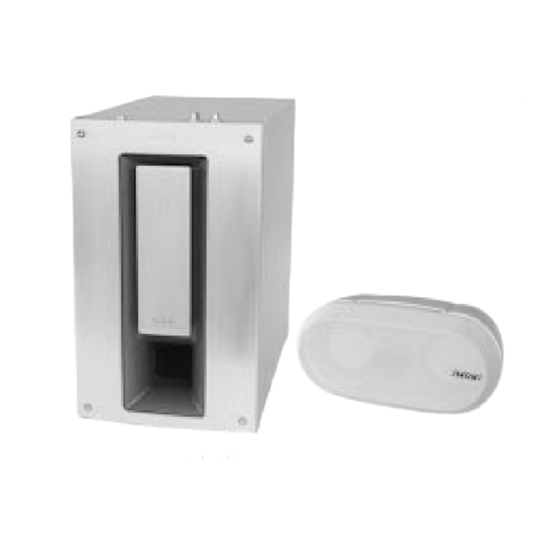
Photo : SA-WMS7
SPECIFICATIONS
Mass
When attached speaker grilles:
When attached to supplied speaker stand:
SS-WMS7 (subwoofer)
System
Speaker system
in.), dome type
Speaker unit
× 2
, balanced drive
Enclosure type
Practical maximum output
Reproduction frequency range
Inputs
LINE IN (input pin jack)
SPEAKER IN (input terminals)
Outputs
LINE OUT (output pin jack)
1
/8 in.) each
SPEAKER OUT (output terminals)
General
Power requirements
5
USA and Canada :
/8 in.) each
Europe :
Others :
3
Power consumptions
/4 in.),
Dimensions (w/h/d)
5
/8 in.),
Mass
SA-VE702/VE705/
WMS7/SS-MS7
Photo : SS-MS7
Supplied accessories
SA-VE705
Approx. 1.3 kg (2lb 14oz) each
Speaker stands (for the front and rear speakers) (4)
Speaker stand (for the center speaker) (1)
Approx. 1.4 kg (3lb 1oz) each,
Screws (for the speaker stands) (10)
(Front (and rear) speakers)
Washers (for the speaker stands) (10)
Approx. 1.4 kg (3lb 1oz)(Center
Brackets (for the front and rear speaker stands) (4)
speaker)
Speaker grilles (5)
Audio connecting cord (1)
Speaker connecting cords, 2.5 m(8 ft
Active subwoofer, magnetically
Speaker connecting cords, 10 m(32 ft
shielded
Woofer : 20 cm (8 in.),
SA-VE702
cone type
Speaker stands (for the front speakers) (2)
Advanded SAW type
Screws (for the speaker stands) (4)
Washers (for the speaker stands) (4)
120 W
Brackets (for the front speaker stands) (2)
Speaker grilles (2)
24 Hz - 150 Hz
Audio connecting cord (1)
Speaker connecting cords, 2.5 m(8 ft
Design and specifications are subject to change
without notice
120 V AC, 60 Hz
220 - 230 V AC, 50/60 Hz
220 - 240 V AC, 50/60 Hz
80 W
Approx. 230 × 380 × 470 mm
/8 × 15 × 18
1
5
(9
/8 in.), including
front grille
Approx. 17 kg
(37 lb 8oz)
MICRO SATELLITE SYSTEM
US Model
Canadian Model
SA-VE705/WMS7/SS-MS7
AEP Model
UK Model
E Model
2
1
/
in.) (5)
2
3
9
/
in.) (2)
4
1
2
/
in.) (4)
2
Advertisement
Table of Contents


Need help?
Do you have a question about the SA-VE702 and is the answer not in the manual?
Questions and answers