Sony SA-VE312 Service Manual
Hide thumbs
Also See for SA-VE312:
- Operating instructions manual (60 pages) ,
- Service manual (13 pages) ,
- Service manual (13 pages)
Table of Contents
Advertisement
SERVICE MANUAL
Ver 1.1 2004. 01
• The SA-VE312 system consists of one unit
of SA-WMS315 and two units of SS-V315.
• The SA-VE315 system consists of one unit
of SA-WMS315, one unit SS-CN315 and
four units of SS-V315.
AUDIO POWER SPECIFICATIONS
POWER OUTPUT AND TOTAL
HARMONIC DISTORTION :
with 8 Ω loads both channels driven, from 20 - 150 Hz; rated
75 W per channel minimum RMS power, with no more than
0.8% total harmonic distortion from 250 mW to rated output.
SS-V315 (f
ront and rear speakers)
Speaker system
Full range, magnetically shielded
× 10 cm (
2 × 4 in.), cone type
Speaker units
5
Enclosure type
Bass reflex
8 Ω
Rated impedance
Power handling capacity
Maximum input power: 100 W
Sensitivity level
87 dB (1W, 1m)
Frequency range
90 Hz - 20,000 Hz
Approx. 68 × 150 × 125 mm
Dimensions (w/h/d)
× 6 × 5 in.), including front
3
(2
/
4
grille
Mass
European model:
Approx. 640 g (1 lb 7 oz) each
Other model:
Approx. 740 g (1 lb 10 oz) each
SS-CN315 (center speaker)
× 2, magnetically
Full range
Speaker system
shielded
× 10 cm (
2 × 4 in.), cone type
Speaker units
5
Enclosure type
Bass reflex
8 Ω
Rated impedance
Power handling capacity
Maximum input power: 120 W
Sensitivity level
89 dB (1W, 1m)
Frequency range
90 Hz - 20,000 Hz
Approx. 301 × 68 × 125 mm
Dimensions (w/h/d)
× 2
× 5 in.), including front
(11
7
/
3
/
8
4
grille
Mass
European model:
Approx. 1.4 kg (3 lb 1 oz) each
Other model:
Approx. 1.5 kg (3 lb 5 oz) each
Sony Corporation
9-929-075-12
2004A16-1
Home Audio Company
© 2004.01
Published by Sony Engineering Corporation
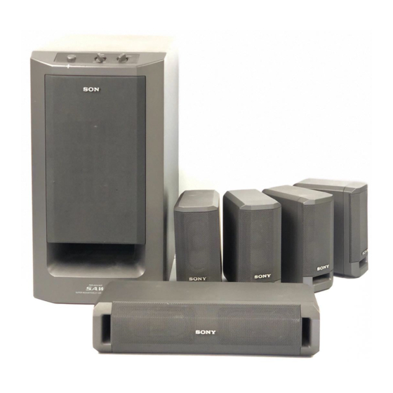
SA-VE312/VE315/WMS315/
Photo: SS-V315
Photo: SA-WMS315
SPECIFICATIONS
SA-WMS315 (subwoofer)
System
Speaker system
Active subwoofer, magnetically
shielded
Speaker unit
Woofer : 16 cm (6
cone type
Enclosure type
Advanded SAW type
Continuous RMS power output
(8 Ω, 20 - 150 Hz, 0.8 % THD)
European model:
50 W
Other model:
75 W
Reproduction frequency range
28 Hz - 200 Hz
High frequency cut-off frequency
200 Hz
Inputs
LINE IN (input pin jack)
SPEAKER IN (input terminals)
Outputs
LINE OUT (output pin jack)
SPEAKER OUT (output terminals)
General
Power requirements
European model:
220 - 230 V AC, 50/60 Hz
Other model:
120 V AC, 60 Hz
Power consumptions
European model:
50 W
Other model:
70 W
Approx. 205 × 385 × 385 mm
Dimensions (w/h/d)
× 15
× 15
(8
1
/
1
/
8
4
front grille
Mass
Approx. 10.5 kg
(23 lb 2 oz)
SS-CN315/V315
Canadian Model
Australian Model
Photo: SS-CN315
Supplied accessories
SA-VE315
Foot pads (20)
Audio connecting cords (1)
3
/
in.),
8
Speaker connecting cords, 10 m (32 ft
Speaker connecting cords, 2.5 m (8 ft
SA-VE312
Foot pads (8)
Audio connecting cords (1)
Speaker connecting cords, 2.5 m (8 ft
Design and specifications are subject to change
without notice
1
/
in.), including
4
MICRO SATELLITE SYSTEM
US Model
AEP Model
UK Model
E Model
3
9
/
in.) (2)
4
1
2
/
in.) (5)
2
2
1
/
in.) (4)
2
Advertisement
Table of Contents


Need help?
Do you have a question about the SA-VE312 and is the answer not in the manual?
Questions and answers