Table of Contents
Advertisement
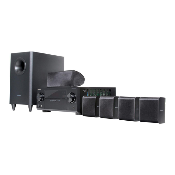
Home Theater Package
HTP-072
Home Cinema Package
HTP-073
AV Receiver
VSX-324-K-P
Subwoofer
S-22W-P
THIS MANUAL IS APPLICABLE TO THE FOLLOWING MODEL(S) AND TYPE(S).
Model
HTP-072
CMXESM
HTP-072
YXE8
HTP-072, HTP-073
VYXE8
HTP-072
DLXE
HTP-072
PWXE
HTP-072
AXQ5
VSX-324-K-P
CMXESM
VSX-324-K-P
YXE8
VSX-324-K-P
VYXE8
VSX-324-K-P
DLXE
VSX-324-K-P
PWXE
VSX-324-K-P
AXQ5
S-22W-P
—————
S-11A-P
—————
HTP-072 and HTP-073 is a Home Cinema Package and consists of VSX-324-K-P, S-22W-P and S-11A-P.
PIONEER CORPORATION
PIONEER ELECTRONICS (USA) INC. P.O. Box 1760, Long Beach, CA 90801-1760, U.S.A.
PIONEER EUROPE NV Haven 1087, Keetberglaan 1, 9120 Melsele, Belgium
PIONEER ELECTRONICS ASIACENTRE PTE. LTD. 253 Alexandra Road, #04-01, Singapore 159936
PIONEER CORPORATION
Type
Power Requirement
AC 120 V
AC 220 V to 230 V
AC 220 V to 230 V
AC 110 V to 127 V/220 V to 240 V
AC 220 V to 230 V
AC 220 V
AC 120 V
AC 220 V to 230 V
AC 220 V to 230 V
AC 110 V to 127 V/220 V to 240 V
AC 220 V to 230 V
AC 220 V
—————
—————
1-1, Shin-ogura, Saiwai-ku, Kawasaki-shi, Kanagawa 212-0031, Japan
2013
Front
Surround
Center
HTP-072
Speaker System
S-11A-P
ORDER NO.
RRV4432
Remarks
K-MZV MAY
2013 Printed in Japan
Advertisement
Table of Contents

Related Manuals for Pioneer VSX-324-K-P


Summarization of Contents
SAFETY INFORMATION
SAFETY PRECAUTIONS
General safety rules for technicians and users, including precautions.
PRODUCT SAFETY NOTICE
Highlights special safety-related characteristics of components and replacement parts.
SERVICE PRECAUTIONS
NOTES ON SOLDERING
Guidelines and recommendations for using lead-free solder and soldering irons.
NOTES ON REPLACING PARTS
Identifies parts difficult to replace as discrete components, recommending Assy replacement.
BASIC ITEMS FOR SERVICE
CHECK POINTS AFTER SERVICING
Confirms recommended checks to maintain product quality after repair.
JIGS LIST
Lists required jigs and their part numbers for diagnosis and firmware updates.
PCB LOCATIONS
LIST OF ASSEMBLIES
Details various PCB assemblies and their corresponding part numbers for different models.
BLOCK DIAGRAMS
OVERALL WIRING AND BLOCK DIAGRAMS
Illustrates main signal flow and overall audio processing system connections.
POWER AND GROUND DIAGRAMS
Shows power (VCC) and ground (GND) distribution across system blocks.
DIAGNOSIS
TROUBLESHOOTING
Provides flowcharts for diagnosing common issues like "No Power" and "No FL DISPLAY".
PROTECTION CIRCUIT
Details overload, DC protection, and temperature detection circuits for system safety.
SERVICE MODE
PROTECTION DETECTION MODES
Explains display, reset modes, and unit operation during protection events.
DISASSEMBLY
VSX-324-K-P DISASSEMBLY
Provides step-by-step procedures for safely disassembling the VSX-324-K-P unit.
EXPLODED VIEWS AND PARTS LIST
PACKING SECTION
Shows exploded views and lists parts for the packing of the S-11A-P, VSX-324-K-P, and S-22W-P.
VSX-324-K-P PARTS LIST
Provides an exploded view and parts list for the VSX-324-K-P main unit.
SCHEMATIC DIAGRAMS
MAIN ASSY SCHEMATICS
Presents the detailed schematic diagrams for the MAIN ASSY across three parts.
D-MAIN ASSY SCHEMATICS
Displays the schematic diagrams for the D-MAIN ASSY, covering digital audio processing.
CPU ASSY SCHEMATIC
Presents the schematic diagram for the CPU ASSY, the unit's main control center.
PCB CONNECTION DIAGRAMS
MAIN and OPTCO ASSYS CONNECTIONS
Illustrates PCB layouts and connector pin assignments for MAIN and OPTCO ASSYS.
CPU ASSY CONNECTIONS
Illustrates the PCB layout and connector pin assignments for the CPU ASSY.
PCB PARTS LIST
LIST OF ASSEMBLIES
Lists major PCB assemblies and their part numbers across different models.
Need help?
Do you have a question about the VSX-324-K-P and is the answer not in the manual?
Questions and answers