Table of Contents
Advertisement
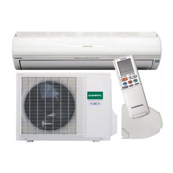
SPLIT TYPE
ROOM AIR CONDITIONER
CEILING WALL
INVERTER
Models
AWHZ14LBC
AOHZ14LBC
AWHZ18LBC
AOHZ18LBC
CONTENTS
SPECIFICATIONS . . . . . . . . . . . . . . . . . . . . 1
OUTLINE AND DIMENSIONS . . . . . . . . . . 2
REFRIGERANT SYSTEM DIAGRAM . . . . 3
CIRCUIT DIAGRAM . . . . . . . . . . . . . . . . . . 4
INDOOR PCB CIRCUIT DIAGRAM . . . . . 5
OUTDOOR PCB CIRCUIT DIAGRAM . . . 8
ERROR CONTENTS . . . . . . . . . . . . . . . . .
DISASSEMBLY ILLUSTRATION . . . . . . .
PARTS LIST . . . . . . . . . . . . . . . . . . . . . . .
type
10
11
14
Advertisement
Table of Contents

Related Manuals for General AWHZ18LBC


Summarization of Contents
Specifications
Electrical Data
Provides power supply and consumption details.
Compressor
Describes compressor type, discrimination, and refrigerant.
Noise Level
Details noise levels for indoor and outdoor units at various speeds.
Dimensions
Indoor Unit Dimensions
Illustrates dimensions for indoor units.
Outdoor Unit Dimensions
Illustrates dimensions for outdoor units.
Refrigerant System Diagram
Model Coverage
Shows the refrigerant flow for specific indoor/outdoor unit models.
Circuit Diagram
Indoor Unit Circuit
Details the electrical circuit for the indoor unit.
Outdoor Unit Circuit
Details the electrical circuit for the outdoor unit.
Indoor PCB Circuit Diagram
PCB Schematic
Electrical schematic for the indoor unit's Printed Circuit Board.
Controller PCB Assy
Controller PCB Schematic
Detailed schematic of the main controller PCB.
Indicator PCB
Indicator PCB Schematic
Circuit diagram for the indicator PCB with LEDs.
Outdoor PCB Circuit Diagram
Outdoor Unit Circuit
Electrical circuit diagram for the outdoor unit.
Outdoor Controller PCB Schematic
Controller PCB Schematic
Detailed schematic for the outdoor unit's controller PCB.
Error Contents
Serial Signal Error
Details serial signal communication errors and their indicators.
Indoor Unit Errors
Covers thermistor, control, and fan motor errors for the indoor unit.
Outdoor Unit Errors
Covers thermistor, control, and fan motor errors for the outdoor unit.
Refrigerant Cycle Error
Errors indicating issues with the refrigerant system.
Disassembly Illustration
Indoor Unit Disassembly
Visual guide for disassembling the indoor unit.
Parts List Indoor Unit
Air Filter
Part number for the air filter.
Evaporator Assy B
Part number for Evaporator Assy B.
Controller PCB Assy
Part number for the Controller PCB Assembly.
Remote Controller Assy
Part number for the Remote Controller Assembly.
Outdoor Unit Parts List
Top Panel Assy
Part number for the top panel assembly.
4-Way Valve
Part number for the 4-way valve.
Compressor Assy
Part number for the compressor assembly.
Expansion Valve Coil
Part number for the expansion valve coil.
Standard Accessories
Wall Hook Bracket
Part number for the wall hook bracket.
Drain Pipe
Part number for the drain pipe.
Remote Control Unit
Part number for the remote control unit.
Battery
Part number for the battery.
Need help?
Do you have a question about the AWHZ18LBC and is the answer not in the manual?
Questions and answers