Table of Contents
Advertisement
Service
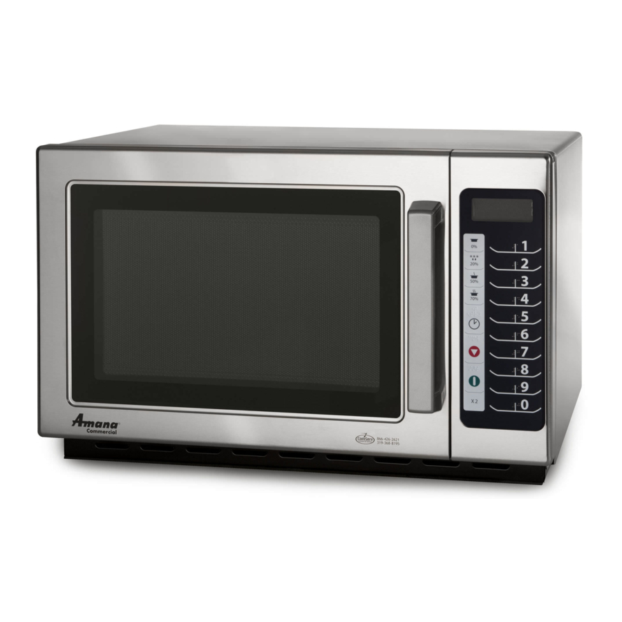
Countertop
Commercial
Microwave
Ovens
This Base Manual covers general information
Refer to individual Technical Sheet
for information on specific models
This manual includes, but is
not limited to the following:
RCS10TS
RCS10DS
MCS10TS
MCS10DS
P2001101M
P2001102M
P2001103M
P2001104M
16400009
November 2010
Advertisement
Table of Contents
Troubleshooting

Related Manuals for ACP RCS10DS


Summary of Contents for ACP RCS10DS
- Page 1 Service Countertop This Base Manual covers general information Refer to individual Technical Sheet for information on specific models Commercial This manual includes, but is not limited to the following: Microwave RCS10TS P2001101M RCS10DS P2001102M MCS10TS P2001103M Ovens MCS10DS P2001104M 16400009...
-
Page 2: Important Information
DANGER—Immediate hazards which WILL result in severe personal injury or death. WARNING—Hazards or unsafe practices which COULD result in severe personal injury or death. CAUTION—Hazards or unsafe practices which COULD result in minor personal injury, product or property damage. 16400009 ©2010 ACP Inc. -
Page 3: Table Of Contents
Measurement With the Outer Panel Removed ..22 Measurement With a Fully Assembled Oven....22 Record Keeping and Notification After Measurement ..........22 Troubleshooting Operating Instructions for Holaday HI1501, HI1510, and HI1710 ........ 23 Testing Procedures ..........24-25 Power Test ..............26 16400009 ©2010 ACP Inc. -
Page 4: Important Safety Information
Read the following information to avoid possible exposure to microwave radiation: The basic design of the ACP Microwave Oven makes it an inherently safe device to both use and service. However, there are some precautions which should be followed when servicing the microwave to maintain this safety. -
Page 5: Save These Instructions
DO NOT use the cavity for storage. DO NOT bags before placing bag in oven. leave paper products, cooking utensils, or food in oven. c. KEEP oven DOOR CLOSED, turn oven off, and SAVE THESE INSTRUCTIONS 16400009 ©2010 ACP inc. - Page 6 DO NOT place any object between the oven front face and the door or allow soil or cleaner d. The oven should NOT be adjusted or repaired by anyone except properly qualified service personnel. SAVE THESE INSTRUCTIONS 16400009 ©2010 ACP Inc.
-
Page 7: Grounding Instructions
Models operate with a 120 supply voltage. When a microwave oven is on a circuit with other equipment, an increase in cooking times may be required and fuses can be blown. NEMA 5-15R/5-15P 120V–15AMP 16400009 ©2010 ACP inc. -
Page 8: Servicing Of Grounded Products
A 120 volt wall outlet must always be wired as shown ohms). When using this scale, it is important that your below. fingers do not touch the metal parts of the test probes. To do so will give a false indication of the ohm reading. 16400009 ©2010 ACP Inc. -
Page 9: General Information
With restricted air servicer, if service is required after warranty expires. flow, oven may not operate properly and life of electrical parts is reduced. Parts and Accessories Radio Interference Purchase replacement parts and accessories over the Microwave operation may cause interference to radio, phone. To order accessories for your product contact television, or similar equipment. Reduce or eliminate your local product distributor or vist the Web site at www. interference by doing the following: acpsolutions.com. • Clean door and sealing surfaces of oven according to instructions in “Care and Cleaning” section. • Place radio, television, etc. as far as possible from oven. • Use a properly installed antenna on radio, television, etc. to obtain stronger signal reception. 16400009 ©2010 ACP Inc. -
Page 10: Troubleshooting Procedures
Uneven cooking. Inconsistent food thickness, • Use plastic wrap or lid. inconsistent fat or m oisture • Stir once or twice while distribution within the food cooking soup, cocoa, milk, etc. products. 16400009 ©2010 ACP Inc. -
Page 11: Electronic Models
Fuse does not Replace blow. Check continuity of Open power Continuity power supply cord supply cord Replace Normal Failed Touch Panel circuit Replace Malfunction of Display do not shown Interlock secondary countdown Switch interlock switch Assembly 16400009 ©2010 ACP Inc. - Page 12 Malfunction of Continuity interlock switch replace secondary interlock switch Replace Check D.C. voltage being Failed touch supplied to RELAY (RY2) coil Panel Replace Approx. Faulty contacts of Control 15 VDC RELAY (RY2) or Board open relay coil 16400009 ©2010 ACP Inc.
- Page 13 Replace Check D.C. voltage being Failed touch supplied to RELAY (RY1) coil control circuit Located on control board Replace Approx Faulty Control 15 VDC contacts or Board RELAY (RY1) or open relay coil 16400009 ©2010 ACP Inc.
- Page 14 NOTE: Before following the particular steps listed above for the touch pad, verify continuity of each wire harness between the touch pad and printed circuit board. Replace Display does Malfunction Check each control not indicate Normal of control pad on touch board. programming board. panel. at all, even if panel is touched. Replace Malfunction membrane Abnormal of membrane keypad. keypad. 16400009 ©2010 ACP Inc.
-
Page 15: Dial Models
Fuse again Replace high voltage transformer NO Continuity If outlet has proper voltage, check Replace power supply cord. continuity of power supply cord. 16400009 ©2010 ACP Inc. - Page 16 Meter with 6V or higher voltage batteries should be used to check the normal direction resistance of the diode Check the isolation of filament NO Continuity Replace high voltage winding of high voltage transformer. transformer. Good Replace magnetron 16400009 ©2010 ACP Inc.
-
Page 17: Electronic Dial Models
(normal) Replace Normal Disconnect one side of the lead Defective high wire connected form high voltage capacitor voltage transformer to the high voltage capacitor and operate Replace the unit Fuse again Defective high blows voltage transformer 16400009 ©2010 ACP Inc. - Page 18 Malfunction of Continuity interlock switch replace secondary interlock switch Replace Check D.C. voltage being Defective touch supplied to RELAY (RY3) coil control circuit Replace Approx. Faulty contacts of 15 VDC RELAY (RY3) or open relay coil 16400009 ©2010 ACP Inc.
- Page 19 Defective high Continuity terminal of high voltage voltage transformer transformer Replace Check D.C. voltage being Defective touch supplied to RELAY (RY1) coil control circuit Approx Replace Faulty 15 VDC contacts or RELAY (RY1) or open relay coil 16400009 ©2010 ACP Inc.
- Page 20 LED lights on touch control circuit board board programming at all, even if the dial is rotated. Abnormal Replace the Malfunction touch of the touch control circuit control circuit 16400009 ©2010 ACP Inc.
-
Page 21: Service Information
This will cause internal arcing and high secondary current if high voltage is applied. R.F. Capacitors - May short to chassis. This condition will also cause loss of high voltage. Output Antenna Ceramic Fins Anode Block Magnet Terminals/R.F. Capacitors Not Replaceable Serial Number 16400009 ©2010 ACP, Inc. -
Page 22: Microwave Leakage Test
3. While measuring the leakage, always use the two inch (5 cm) spacer supplied with the probe. 4. Press the start pad or turn on the timer and with the magnetron oscillating, measure the leakage by holding the probe perpendicular to the surface being measured. 16400009 ©2010 ACP, Inc. -
Page 23: Troubleshooting
This could cause possible probe burn-out. Greatest leakage is generally found at the corners. After maximum leakage is established to be within the meter scale range, then probe may be moved horizontally around the door surface. 16400009 ©2010 ACP, Inc. -
Page 24: Testing Procedures
Test continuity of wires Indicates continuity Electronic control Test interlock assembly switches. If interlock switch assembly and board Test cavity TCO. cavity TCO is operating correctly. If the control board still has no display, replace control board. 16400009 ©2010 ACP, Inc. - Page 25 Primary – Terminals 1 - 2 ....Indicates continuity Secondary – Terminals 5 - 6 ....Indicates continuity After verifying or replacing the module, re-connect wires to switch and check operation of monitor circuit before operating the oven. 16400009 ©2010 ACP, Inc.
-
Page 26: Power Test
17 ....1700 25 ....2500 9.5 .... 1700 13.5 ..2500 18 ....1800 27 ....2700 10 ..... 1800 15 .... 2700 19 ....1900 30 ....3000 10.5 ..1900 16.5 ..3000 16400009 ©2010 ACP, Inc. -
Page 27: Disassembly Procedures
These components must be replaced for proper circulation of air over the components and through the oven cavity. Non-insulated terminals: Use a small blade screwdriver to depress locking-tab and pull on terminal. DO NOT PULL ON WIRE. 16400009 ©2010 ACP Inc. -
Page 28: Door Assembly
A microwave leakage test must be performed anytime prying choke cover from oven door. a door assembly is removed, replaced, disassembly, or adjusted for any reason. 4. Slide latch assembly downward and pull away from door frame to release. 16400009 ©2010 ACP Inc. -
Page 29: Control Removal (Electronic)
3. Open oven door. 4. Remove screw securing control panel to cavity. Lift control panel up and out to release tabs. 5. Remove timer knob from timer. 6. Remove screws securing timer to control panel and 16400009 ©2010 ACP Inc. -
Page 30: Interlock Assembly
High Voltage Capacitor Removal 1. Disconnect power to oven and remove outer case, (see "Outer Case" procedure). 2. Discharge high voltage capacitor. 3. Remove and label wire leads from capacitor terminals. 16400009 ©2010 ACP Inc. -
Page 31: Diode
2. Discharge high voltage capacitor, (see "High Voltage Capacitor" section). 3. Remove terminal plug from filament terminals. 4. Remove screws securing magnetron cutout bracket to magnetron. 5. Remove screw securing wire support from magnetron. 6. Remove screws securing magnetron to the wave guide. 16400009 ©2010 ACP Inc. -
Page 32: Stirrer Motor
3. Disconnect wire terminals from thermal fuse. 4. Remove screw securing thermal fuse to oven cavity. 5. Replace component and reverse procedure to reassemble. NOTE: When reconnecting wiring to thermal fuse the connectors must be tight. 16400009 ©2010 ACP Inc.
Need help?
Do you have a question about the RCS10DS and is the answer not in the manual?
Questions and answers