
Related Manuals for Trane TUD060


Summarization of Contents
General Features
Natural Gas Models
Furnace designs certified by AGA & CSA for natural and L.P. gas. Limit setting and rating data established under ANSI standards.
Safe Operation
Solid-state control monitors flame presence in heating mode. Dual solenoid gas valve for extra safety.
Quick Heating
Durable, heavy-gauge aluminized steel heat exchanger transfers heat quickly for warm air.
Burners
Multi-port In-shot burners offer quiet, efficient service. All models can be converted to L.P. gas.
Integrated System Control
Provides total control of furnace limits, blowers, gas valve, flame control; includes self-diagnostics.
Air Delivery
4-speed, direct drive blower motor provides airflow for heating/cooling. Blower door safety switch included.
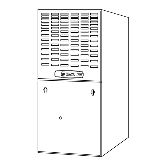
Styling
Heavy gauge steel, "wrap-around" cabinet construction with baked-on enamel finish. Lined with foil-faced fiberglass insulation.
Features And General Operation
Uses adaptive Hot Surface Ignition, eliminating pilot waste. Front service access for all components.
Features and Benefits
Standard Equipment
Lists features included with the XR 80 furnace, such as igniter, control, heat exchanger, filters, etc.
Optional Equipment
Lists accessories available for the XR 80 furnace, like thermostats, air filters, and coil enclosures.
General Data
Product Specifications
Detailed technical specifications for various XR 80 models, covering ratings, blower, heat exchanger, and dimensions.
Performance Data
Furnace Airflow vs. Static Pressure
Tables detailing furnace airflow (CFM) at various static pressures for different speed taps and models.
Performance Data
CFM vs. Temperature Rise
Tables showing cubic feet per minute (CFM) at different temperature rises for various furnace models.
Field Wiring
Field Wiring Diagram for Heating Only
Illustrates wiring connections for heating-only configurations, including thermostat and accessories.
Field Wiring Diagram for Single Stage Heating/Cooling
Shows wiring for single-stage heating/cooling without an outdoor transformer, detailing connections.
Twinning Field Wiring
Twinning Diagram for 1-Stage Heating Only Thermostat
Wiring diagram for twinning two furnaces with a single-stage heating-only thermostat.
Twinning Diagram for 1-Stage Heating/Cooling Thermostat
Wiring diagram for twinning furnaces with a single-stage heating/cooling thermostat.
TUD-C Outline Drawing
Model Dimensions
Table showing dimensional data (A, B, C, D) for various TUD-C furnace models.
Minimum Clearances to Combustible Materials
Specifies required clearances for upflow, horizontal closet, and horizontal alcove installations.
Electrical Data
Schematic Diagrams for Gas Furnaces
Provides wiring schematic diagrams for gas furnaces, showing components and connections.
Legend and Fan Motor Speed Taps
Explains symbols used in diagrams and lists speed tap assignments for the ID fan motor.
Need help?
Do you have a question about the TUD060 and is the answer not in the manual?
Questions and answers