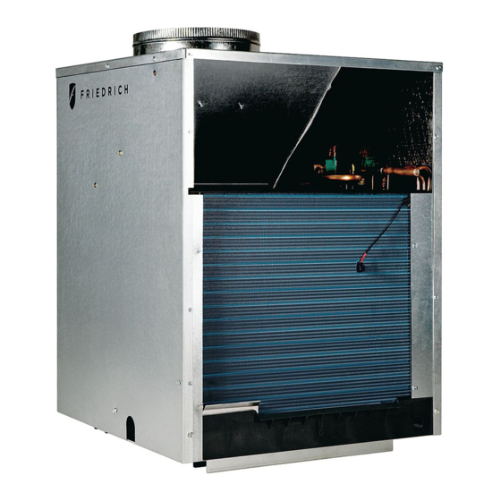
Summarization of Contents
General Specifications
Model Number Identification Guide
Guide for identifying Vert-I-Pak model numbers based on series, design, capacity, and voltage.
VERT-I-PAK Chassis Specifications
Details on chassis dimensions, cooling current, minimum circuit amps, and power connection.
Electrical Data
Provides electrical data including voltage, refrigerant, chassis dimensions, and duct/drain connections.
Installation
Utility Closet Dimensions
Recommended dimensions and clearances for utility closet installations.
Wall Plenum and Architectural Louver Installation
Instructions for installing wall plenum and architectural louvers for unit mounting.
Drain Pan Installation
Guidance on installing the drain pan and connecting the condensate drain.
Condensate Disposal System
Details on the three-stage condensate disposal system and its operation.
Indoor Return Air Grille Installation
Options and requirements for installing indoor return air grilles.
Ductwork Preparation
Information on preparing ductwork, including ESP limits and CFM determination.
Chassis Installation
Steps for properly installing the Vert-I-Pak chassis into the wall plenum.
Remote Thermostat Operation
Remote Thermostat
Overview of controlling the unit with a single-stage remote wall-mounted thermostat.
Thermostat Connections
Details on thermostat terminal connections for unit control.
Electrical & Thermostat Wiring Diagrams
Diagrams illustrating typical thermostat and electrical wiring for the unit.
Chassis Operation
Fresh Air Door
Description of the fresh air intake system and its CFM capability.
Low Ambient Protection
Explanation of the thermistor-based protection against low suction temperatures.
Room Freeze Protection
Details on enabling and functioning of the room freeze protection feature.
Emergency Heat Override
Procedure for switching a heat pump unit to electric heat mode only.
Emergency Heat Operation
How the unit provides heat via resistance heater in case of compressor failure.
Service & Warranty
Servicing/Chassis Quick Changeouts
Procedures for minor electrical service and major chassis replacement.
Routine Maintenance
Guidelines for performing regular maintenance, including filter replacement.
Error Codes
Chart listing error codes, their translations, actions, and possible causes.
Factory Dipswitch Configuration
Diagram showing the location and function of factory dip switches.
Warranty
Information on warranty service and contact details for repairs.


Need help?
Do you have a question about the VHA12K34 Series and is the answer not in the manual?
Questions and answers