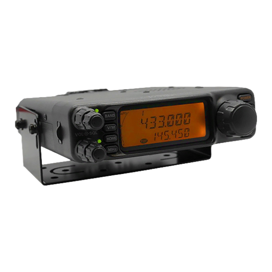
Yaesu FT-7100M Operating Manual
Vhf/uhf dual band fm transceiver
Hide thumbs
Also See for FT-7100M:
- Operating manual (57 pages) ,
- Operating manual (57 pages) ,
- Technical supplement (68 pages)
Table of Contents
Advertisement
Quick Links
O
M
PERATING
ANUAL
VERTEX STANDARD CO., LTD.
4-8-8 Nakameguro, Meguro-Ku, Tokyo 153-8644, Japan
VERTEX STANDARD
US Headquarters
17210 Edwards Rd., Cerritos, CA 90703, U.S.A.
International Division
8350 N.W. 52nd Terrace, Suite 201, Miami, FL 33166, U.S.A.
YAESU EUROPE B.V.
P.O. Box 75525, 1118 ZN Schiphol, The Netherlands
YAESU UK LTD.
Unit 12, Sun Valley Business Park, Winnall Close
Winchester, Hampshire, SO23 0LB, U.K.
YAESU GERMANY GmbH
Am Kronberger Hang 2, D-65824 Schwalbach, Germany
VERTEX STANDARD HK LTD.
11th Floor Tsim Sha Tsui Centre, 66 Mody Rd.,
Tsim Sha Tsui East, Kowloon, Hong Kong
Advertisement
Table of Contents

Subscribe to Our Youtube Channel
Related Manuals for Yaesu FT-7100M


Summary of Contents for Yaesu FT-7100M
- Page 1 17210 Edwards Rd., Cerritos, CA 90703, U.S.A. International Division 8350 N.W. 52nd Terrace, Suite 201, Miami, FL 33166, U.S.A. YAESU EUROPE B.V. P.O. Box 75525, 1118 ZN Schiphol, The Netherlands YAESU UK LTD. Unit 12, Sun Valley Business Park, Winnall Close Winchester, Hampshire, SO23 0LB, U.K.
-
Page 2: Table Of Contents
Contents Introduction ............1 DTMF Autodialer Operation ......28 Specifications ............ 2 Transmitter Time-Out Timer (TOT)....30 Accessories & Option ........3 Memory Operation ........31 Installation ............4 Memory Storage ..........31 Preliminary Inspection ........4 Storing independent Transmit Frequencies Installation Tips .......... -
Page 3: Introduction
Watts of power output on the 144 MHz Amateur band, and 35 Watts on the 430 MHz band. The high power output of the FT-7100M is produced by its 2SK3478 Power MOS FET amplifier, with a direct-flow heat sink and thermostatically-controlled cooling fan maintaining a safe temperature for the transceiver’s circuitry. -
Page 4: Specifications
5% THD AF Output Impedance: 4-16 Specifications are subject to change without notice, and are guaranteed within the 144 and 430 MHz amateur bands only. Frequency ranges will vary according to transceiver version; check with your dealer. FT-7100M Operating Manual... -
Page 5: Accessories & Option
PC Programming Software Availability of accessories may vary. Some accessories are supplied as standard per local requirements, while others may be unavailable in some regions. Consult your Yaesu dealer for details regarding these and any newly-available options Connection of any non-Yaesu- approved accessory, should it cause damage, may void the Limited Warranty on this appa- ratus. -
Page 6: Installation
Do not install the transceiver on top of another heat-generating device (such as a power supply or amplifier), and do not place equipment, books, or papers on top of the FT-7100M. Avoid heating vents and window locations that could expose the transceiver to excessive direct sunlight, especially in hot climates. -
Page 7: Safety Information
AFETY NFORMATION The FT-7100M is an electrical apparatus, as well as a generator of RF (Radio Frequency) energy, and you should exercise all safety precautions as are appropriate for this type of device. These safety tips apply to any device installed in a well-designed amateur radio station. -
Page 8: Antenna Considerations
NTENNA ONSIDERATIONS The FT-7100M is designed for use with antennas presenting an impedance of near 50 Ohms at all operating frequencies. The antenna (or a 50 W dummy load) should be connected whenever the transceiver is turned on, to avoid damage that could otherwise result if trans- mission occurs accidentally without an antenna. - Page 9 The use of the shortest possible length of the highest quality co- axial cable that fits within your budget will ensure the best performance from your FT- 7100M. FT-7100M Operating Manual...
-
Page 10: Mobile Installation
NSTALLATION OBILE NSTALLATION The FT-7100M must only be installed in vehicles having a 13.8 Volt negative ground electri- cal system. Mount the transceiver where the display, controls, and microphone are easily accessible, using the supplied MMB-36 mounting bracket. The transceiver may be installed in almost any location, but should not be positioned near a heating vent nor anywhere where it might interfere with driving (either visually or mechani- cally). -
Page 11: Mobile Power Connections
– it is there to protect you, your transceiver, and your vehicle’s electrical system. Warning! Never apply AC power to the power cable of the FT-7100M, nor DC voltage greater than 15.8 Volts. When replacing the fuse, only use a 15-A fast-blow type. Failure to observe these safety precautions will void the Limited Warranty on this product. -
Page 12: Base Station Installation
TNC, if it is designed for multiple-radio use, by connecting the TNC “Radio 1” port to the 1200 bps lines on the FT-7100M, and the “Radio 2” port to the 9600 bps lines. The pin connections of the Data connector are shown below. - Page 13 Packet data rate (1200 or 9600 bps) independently for each band. If you have trouble getting your FT-7100M to respond correctly during packet operation, check to be certain that you do not have Menu #19 (PCKT) set to the wrong data rate.
-
Page 14: Front Panel Controls, Switches
This LED glows Green when a signal is being received on the “sub” band channel. Command Keys These four keys select many of the most important operating features on the FT-7100M. [ BAND ] Key: Pressing this key switches “main” band control between the VHF band and UHF band. - Page 15 Main Dial Knob This 24-position detented rotary switch is the main tuning dial for the transceiver. It used for most tuning, memory selection, and function setting tasks on the FT-7100M. Function Keys These four keys operate in a manner similar to the Command Keys just described.
-
Page 16: Lcd
Repeater Shift Digtal Code Squelch Memory Tune 9600 bps Data Operation Low Tx Power S&PO Meter Alert Ringer Keypad/DIAL Lock Enabled Packet Operation Scan Skip Memory PTT Lock Time-Out Timer Sub Band Frequency Main Band Frequency APO Timer FT-7100M Operating Manual... -
Page 17: Rear Panel Connections
Controller (TNC) for 1200 bps or 9600 bps operation. The pinout is detailed on page 10. EXT SP Jack This 2-conductor, 3.5-mm mini phone jack provides audio output for an optional speaker (impedance is 4 ~ 16 ). Inserting a plug into this jack disables audio from the internal speaker. FT-7100M Operating Manual... -
Page 18: A6J Microphone
UP/DWN Button Press (or hold in) either of these buttons to tune (or scan up or down) the band or through the memory channels. In many ways, these buttons emulate the function of the (rotary) Main Dial knob. FT-7100M Operating Manual... -
Page 19: B6Js
In many ways, these buttons emulate the function of the (rotary) Main Dial knob. Notice If you replace the mocrophone from the MH-48 to MH-42 or vice versa, perfome B6JS Menu # 17 (MIC ). See page 52 for details. FT-7100M Operating Manual... -
Page 20: Operation
RF Squelch A special RF Squelch feature is provided on the FT-7100M. This feature allows you to set the squelch so that only signals exceeding a certain S-meter level will open the squelch. To set up the RF Squelch circuit for operation, use the following procedure: 1. -
Page 21: Frequency Display And Band Change
To enter 146.520 MHz, press [ 1 ] à [ 4 ] à [ 6 ] à [ 5 ] à [ 2 ] à [ 0 ] . To enter 433.000 MHz, press [ 4 ] à [ 3 ] à [ 3 ] à [ # ] . FT-7100M Operating Manual... -
Page 22: Channel Step Selection
4. Rotate the Main Dial knob to select “ON.” 5. Press and hold in the [ BAND ] key for 1/2 second to save the new setting and exit to normal operation. To disable the VFO tracking function, select “OFF ” in step 4 above. FT-7100M Operating Manual... -
Page 23: Receiver Muting
To disable the Mute feature, select “OFF” in step 4 above. VHF-VHF (V-V) or UHF-UHF (U-U) Operation The FT-7100M typically operates on one VHF and one UHF frequency. However, the FT- 7100M may be configured to operate either in a V-V or U-U mode, if needed. Operation in either of these modes is easily enabled: r If the “main”... -
Page 24: Lock Feature
4. Rotate the Main Dial knob to select a comfortable brightness level (DIM 1 ~ DIM 7 , or OFF). 5. Press and hold in the [ BAND ] key for 1/2 second to save the new setting and exit to normal operation. FT-7100M Operating Manual... -
Page 25: Transmission
OFF : PTT lock feature is off. 5. Press and hold in the [ BAND ] key for 1/2 second to save the new setting and exit to normal operation. To cancel the PTT lock feature, select “OFF” in step 4 above. FT-7100M Operating Manual... -
Page 26: Repeater Splits
¦ Manual selection of preset repeater shifts. Automatic Repeater Shift (ARS) The ARS (Automatic Repeater Shift) feature in the FT-7100M allows easy and convenient repeater operation by automatically activating the repeater shift function whenever you tune within a standard repeater sub-band. The ARS function is preset at the factory to conform to the band-plans for the country to which it is exported. -
Page 27: Separate Transmit Frequency Memories
If you may assign the “Repeater Shift” feature to one of the microphone’s programming buttons (such as [ P1 ] ), you may activate the “standard” repeater shift by pressing the programmable button assigned to this function. See page 43 for details regarding of the microphone button’s functions. FT-7100M Operating Manual... -
Page 28: Tone Squelch System
“ENC/DEC,” or “ ” is activated) or DCS code (when “DCS” is activated). 3. Wait a few seconds: the display will revert to its normal status, and your new CTCSS or DCS information will be DSC Code Squelch saved. FT-7100M Operating Manual... -
Page 29: Tone Search Scanning
) button on the microphone to transmit a 1750 Hz Burst Tone for repeater access. B6JS If you own a non-European version of the FT-7100M, but plan on visiting a country which requires a 1750 tone for repeater access, you may use menu #20 to set up the [ P1 ] (MH- ) or [ ACC ] (MH-42 ) button for 1750 Hz Tone operation. -
Page 30: Dtmf Tone Generation
Just press the PTT switch, and hold it in, while pressing the desired keys. DTMF Autodialer Operation Sixteen DTMF Autodialer memories are available on the FT-7100M. These DTMF Autodialer memories can store up to 16 digits of a telephone number for repeater autopatch or other use. - Page 31 Important Note Do not attempt to utilize the DTMF features, either manually or Auto-dialing, while you are driving. Always park you car before dialing, in the interest of safety to you, your passengers, and other drivers. FT-7100M Operating Manual...
-
Page 32: Transmitter Time-Out Timer (Tot)
(during transmission), “ ” will begin blinking. Then, if you continue pressing the PTT switch until the selected TOT time interval, transmission will case, and you will hear the alert beeper sound until you release the PTT switch. FT-7100M Operating Manual... -
Page 33: Memory Operation
1 above. 4. Press and hold in the PTT switch; while holding it in, press and hold in the [ V/M ] key for 1/2 second once more (this does not key the transmitter). FT-7100M Operating Manual... -
Page 34: Recalling Memories
Example: To recall memory channel #5, press [ 5 ] à [ Ú ] . To recall memory channel #100, press [ 1 ] à [ 0 ] à [ 0 ] à [ Ú ] . FT-7100M Operating Manual... -
Page 35: Memory Offset Tuning
Once you have recalled a particular memory channel, you may easily tune off that channel, as though you were in the “VFO” mode. 1. With the FT-7100M in the “MR” (Memory Recall) mode, select the desired memory channel. 2. Now press the [ MHz ] key momentarily; the “... -
Page 36: Transferring Memory Channels
EMORY HANNELS There are 262 programmable memory channels in the FT-7100M. These consist of 120 regular memories and 11 special-purpose memories (L1 - L5, U1 - U5, and HOME) for each band. However, if you need more memories on a particular band, you can transfer (regular) memories from one group to another, as needed (such as VHF: 190 channels, UHF: 50 chan- nels). -
Page 37: Scanning Feature
EATURES CANNING PERATION The FT-7100M’s microprocessor-based scanning feature allows quick scanning of the memory channels, or sweeping of a band, looking for activity. Before activating the scanner, make sure that the SQL control is set to silence the back- ground noise when no signal is present. If the noise is not squelched, the transceiver will “think”... -
Page 38: Memory Skip Scanning
To skip a channel temporarily, press the [ TONE ] key momentarily while the scanner has stopped on the channel to be skipped. The scanner will instantaneously resume, and that channel will not be scanned during this scanning session. FT-7100M Operating Manual... -
Page 39: Programmable Band-Scan Limit
VFO mode, but operation will be restricted to the range between Memory channels “L1” and “U 1 .” Five pairs of Band Limit memories, labeled “L1/U 1 ” through “L5/U 5 ,” are available. You therefore can set a number of operating sub-bands, if you like. FT-7100M Operating Manual... -
Page 40: Priority Channel Operation
HOME Priority 1. Recall the memory channel which you wish to use as the “priority” frequency. 2. Now set the FT-7100M for operation on the HOME channel that is on the same band as the selected HOME channel. 3. Press and hold in the [ REV ] key for 1/2 second to activate the HOME Priority mode; the “PRI”... -
Page 41: Smart Search
Search to a VFO/Memory, or if you initiate a new Smart Search. Smart Search also does not store CTCSS or DCS information; if you cannot access a repeater found during Smart Search, you may need to investigate possible access tones. FT-7100M Operating Manual... -
Page 42: Arts: Auto Range Transponder System
A high tone beep will sound every time a polling transmission is received from the other station, and a low beep will sound once when the other station goes out of range. OFF: ARTS operation is disabled. FT-7100M Operating Manual... -
Page 43: Cw Id (Morse Identifier) Setup
4. Rotate the Main Dial knob to change the display to “ON.” 5. Press and hold in the [ BAND ] key for 1/2 second to save the new setting and exit to normal operation. 6. To disable the CW IDer, select “OFF” in step 4 above. FT-7100M Operating Manual... -
Page 44: Miscellaneous Settings
“ ” will begin blinking and an alert beeper will sound. If you don’t press a key in the next three minutes, the transceiver will turn itself off. FT-7100M Operating Manual... -
Page 45: Programming The Microphone Button Functions
ICROPHONE UTTON UNCTIONS Default FT-7100M button functions have been assigned (at the factory) to the microphone’s buttons*. These may be changed by the user, if you wish to define another function for a particular button or buttons To change the assignment of a button’s function: 1. -
Page 46: Dcs Code Inversion
TX R: Encoder Reverse (Inverted); Decoder Normal TRX R: Encoder Reverse (Inverted); Decoder Reverse (Inverted) 5. Press and hold in the [ BAND ] key for 1/2 second to save the new setting and exit to normal operation. FT-7100M Operating Manual... -
Page 47: External Speaker Selection
5. Press and hold in the [ BAND ] key for 1/2 second to save the new configuration and exit to normal operation. Some or all transceiver settings can be reset to their factory-default states using one of the following power-on routines: FT-7100M Operating Manual... -
Page 48: Microprocessor Reset Procedures
Menu #8 (DCS C ), 19 (PCKT), 26 (SHIFT), 27 (STEP ), 29 (TONEF) r CPU Master Reset for All Memories and Menu Settings Press and hold in the [ V/M ] , [ MHz ] , and [ REV ] keys while turning the transceiver on. FT-7100M Operating Manual... -
Page 49: Cloning
LONING You can transfer all data stored in one FT-7100M to another FT-7100M by utilizing the handy “Cloning” feature. This requires a user-constructed Cloning cable which connects the DATA jacks on the two transceivers, as shown below. To clone from one transceiver to another, use the following procedure: 1. -
Page 50: Menu System
YSTEM The FT-7100M’s Menu System allows a number of transceiver operating parameters to be custom-configured for your operating requirements. The Menu is easy to active and set, using the following basic procedure: 1. Press and hold in the [ BAND ] key for 1/2 second to activate the “Menu” mode. - Page 51 Sets the Time-Out Timer OFF/1 ~ 30 minutes 6 minutes TXNAR Reducing the MIC Gain (and Deviation) ON/OFF VFOTR Enables/disables the VFO Tracking ON/OFF feature Selects the receiving mode (VHF band) AUTO/INH/AM AUTO ø: Depens on transceiver version FT-7100M Operating Manual...
-
Page 52: Menu Selection Details
Menu Item 6 [ CWIDW ] Function: Programming a callsign into the CW IDer. Menu Item 7 [ DIM ] Function: Setting the front panel display’s illumination level. Available Values: DIM1 ~ DIM7, or OFF Default Setting: DIM1 (Brightest illumination) FT-7100M Operating Manual... - Page 53 Function: Setting the DTMF Autodialer delay time. Available Values: 50/250/450/750/1000 ms Default Setting: 450 ms Menu Item 13 [ DTMFS ] Function: Setting the DTMF Autodialer sending speed. Available Values: 50/75/100 ms Default Setting: 50 ms (High Speed) FT-7100M Operating Manual...
- Page 54 Available Values: SQL OFF, TCALL, RPTR, PRI, LOW, TONE, MHz, REV, HOME, BAND, VFO/MR Default Setting: USA version; BAND, European version; TCALL Note: [ P1 ] button for MH-48 , [ ACC ] button for MH-42 B6SJ FT-7100M Operating Manual...
- Page 55 Menu Item 26 [ SHIFT ] Function: Sets the magnitude of the Repeater Shift. Available Values: 0.00 ~ 99.50 MHz (50 kHz step) Default Setting: Depends on transceiver version. Note: This Menu item can be set independently for each band. FT-7100M Operating Manual...
- Page 56 Menu Item 30 [ TSRCH ] 250.3 254.1 – – – – Function: Activates the CTCSS Tone Search Scanner. Menu Item 31 [ TOT ] Function: Sets the Time-Out Timer. Available Values: 1 ~ 30 minutes, or OFF Default Setting: 6 minutes FT-7100M Operating Manual...
- Page 57 Menu Item 34 [ AM ] Function: Selects the receiving mode on the VHF band. Available Values: AUTO/INH/AM Default Setting: AUTO (AM in Aeronautical Bands, FM elsewhere) Note: The “INH” option locks reception in the FM mode. FT-7100M Operating Manual...
- Page 58 FT-7100M Operating Manual...
- Page 59 1. Changes or modifications to this device not expressly approved by VERTEX STANDARD could void the user’s authorization to operate this device. 2. This device complies with part 15 of the FCC Rules. Operation is subject to the following two conditions; (1) this device may not cause harmful interference, and (2) this device must accept any interference including interference that may cause undesired operation.
- Page 60 Copyright 2001 No portion of this manual VERTEX STANDARD CO., LTD. may be reproduced All rights reserved. without the permission of VERTEX STANDARD CO., LTD. Printed in Japan 0103u-CY E H 0 3 M 1...
Need help?
Do you have a question about the FT-7100M and is the answer not in the manual?
Questions and answers