Sign In
Upload
Manuals
Brands
SIMRAD Manuals
Sonar
SX90 - INSTALLATION REV C
SIMRAD SX90 - INSTALLATION REV C Manuals
Manuals and User Guides for SIMRAD SX90 - INSTALLATION REV C. We have
1
SIMRAD SX90 - INSTALLATION REV C manual available for free PDF download: Installation Manual
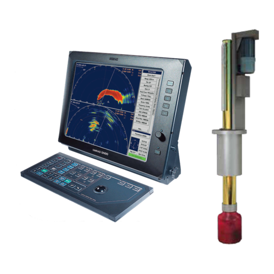
SIMRAD SX90 - INSTALLATION REV C Installation Manual (246 pages)
Fish finding sonar
Brand:
SIMRAD
| Category:
Sonar
| Size: 8 MB
Table of Contents
Table of Contents
5
About this Manual
13
Simrad Sx90 Fish Finding Sonar
15
Basic Information
15
Main Units
16
Wheelhouse Units
16
Sonar Room Units
17
Installation Procedure
18
System Diagram
20
Scope of Supply
21
Additional Required Items
21
Colour Display
21
Uninterrupted Power Supply (UPS)
21
Installation Trunk
23
Speed Log
23
Course Gyro
23
Additional Optional Items
23
Optional Hull Units and Installation Trunks
24
Optional Functionality
25
Other Peripheral Equipment
25
Optional Audio Output
27
General Supply Conditions
29
Equipment Responsibility
29
Receipt, Unpacking and Storage
29
General Installation Requirements
30
Approval by Classification Society
30
Supply Power
30
Compass Deviation
30
Noise Sources
30
Dry Docking
31
Wiring
31
Installation Planning
32
About Installation Drawings
32
Location of the Hull Unit
33
Sonar Room Requirements
34
Sonar Room Arrangement Example
36
Sonar Trunk Installation
38
Mounting the Sonar Trunk
39
Sonar Trunk Installation Principles
40
Sonar Trunk Protection
40
Sonar Trunk Installation Measurements
43
Hull Unit Installation
44
Hull Unit Outline Dimension Drawings SX90 Hull Unit Dimensions
44
SX90/SX91 Mounting Trunk Dimensions
44
SX90/SX91 Optional Trunk Dimensions
44
SX91 Hull Unit Dimensions
44
SX92 Hull Unit Dimensions
44
SX92 Mounting Trunk Dimensions
44
SX92 Optional Trunk Dimensions
44
SX93 Hull Unit Dimensions
44
SX93 Mounting Trunk Dimensions
44
Hull Unit Models Overview
45
SX93 Optional Trunk Dimensions
45
SX90/SX91 Blind Cover Dimensions
45
SX92 Blind Cover Dimensions
45
How to Unpack the Hull Unit from Its Transport Box
46
Note
46
Hull Unit Mounting
47
Bleeding Air Cock
49
Mechanical Support
49
Transducer Alignment
49
Hull Unit Installation Check List
50
Transceiver Unit Installation
51
Transceiver Unit Installation Procedure
51
Transceiver Unit Preparations
51
Wheelhouse Units Installation
55
Physical Location of Wheelhouse Units
55
Maximum Distances between the Units
58
Installation of the Display Unit
59
Installation of the Operating Panel
59
Installation of the Processor Unit
60
Installation of the Beamformer Unit
61
Installation of the Interface Unit
62
Installation of the Audio System
63
Ups Installation
64
Cable Layout and Interconnections
65
Cable Plan
66
List of Cables
68
Table of Contents
73
Cable Procedures
74
Connect AC Mains to the Uninterrupted Power Supply
75
Connect the Video Cable from the Processor Unit to the Colour Display
76
Connect the USB Cable from the Operating Panel to the Processor Unit
77
Connect the Operating Panel "Dual Cable
78
Connect the Two Cables from the Interface Unit to the Processor Unit
79
Connect the Processor Unit to the Beamformer Unit
80
Connect AC Mains and Ground to the Processor Unit
81
Connect AC Mains and Ground to the Beamformer Unit
82
Connect AC Mains to the Colour Display
83
Connect AC Mains to the Transceiver Unit
84
Connect Ground to the Interface Unit
85
Unit
85
Connect Ground to the Operating Panel
86
Connect the Beamformer Unit to the Transceiver Unit
87
It Is very Important that a CAT-6 (or CAT-7) Ethernet Cable Is Used. Cables with Lower Bandwidth Capacity will Reduce the Sonar Performance
87
Connect AC Mains to the Motor Control Unit
88
This Cable Must be Provided by the Installation Shipyard
88
Connect the Transceiver Unit to the Motor Control Unit
89
Motor Control Unit
89
Connect AC Mains to the Heat Exchanger
90
Connect the Ethernet Cable for Scientific Output
91
Connect Cable to External Audio System
91
Transducer Cable
92
Installation of Interface Cables to Peripheral Equipment
92
References to Cable Details and Drawings
92
RJ45 Ethernet, Straight
93
Start-Up Procedures
94
Starting up the Hull Unit
94
Hull Unit Familiarization
95
Motor Control Unit Familiarization
96
Functional Check
97
Apply 3-Phase AC Power
98
Check the Hoist Motor's 3-Phase AC Connections
99
Check the 3-Phase Connection for Correct Rotation Direction
100
Check the Contactor Operation
101
Functional Check to Verify Correct Hoist and Lower Functionality
102
Starting up the Wheelhouse Units
104
Checking the Operating Panel
106
Functional Test
106
Starting up the Transceiver Unit
114
Checking the Hoist/Lower System
115
Preparations
116
Select the Hull Unit to be Used
116
Checking the Bridge Functions
117
Checking the Sonar Room Functions
120
Perform Self-Noise Test
120
Starting up the Sonar System
121
Preparations
122
Actions on the Bridge
123
Actions in the Sonar Room
124
Alignment of the Sonar Picture
124
Adjusting the Stabilisation Sensor Offset
126
Defining Own Ship Parameters
127
Specify Ship Dimensions
127
Specify Instrument Position Offsets
128
Interfacing Peripheral Equipment
130
Interface Settings
130
Default Interface Settings
130
How to Change the Interface Settings
131
How to Monitor the Traffic on a Serial Line
132
Simrad SX90
132
Installation Procedures
133
Connecting the Speed Log
133
Connecting the Course Gyro
135
Test Procedures
136
Speed Log Interface Test
136
Course Gyro Interface Setup and Test
138
Positioning System Interface Setup and Test
139
Echo Sounder System Interface Setup and Test
139
Trawl System Interface Setup and Test
140
Catch Monitoring Interface Setup and Test
141
Radio Buoy System Interface Setup and Test
141
Current Meter Interface Setup and Test
142
Nmea
142
Final Tests and Measurements
143
Source Level (SL) Measurements
143
Preparations
144
Operational Mode
144
Test Procedure
145
Finalizing the Procedure
145
Source Level Test Results
146
Receiving Voltage Response (VR) Measurements
147
Preparations
147
Test Procedure
147
Finalizing the Procedure
148
Test Results
148
Noise/Speed Curve Measurements
149
Power Specifications
153
Technical Specifications
153
Weights and Outline Dimensions
154
Environmental Specifications
155
Drawing File
157
Transceiver Unit Dimensions
158
Interface Unit Dimensions
159
MC80 Processor Unit Dimensions
160
MC81 Beamformer Unit Dimensions
161
Operating Panel Dimensions
162
SX90 Hull Unit Dimensions
163
SX91 Hull Unit Dimensions
164
SX92 Hull Unit Dimensions
165
SX93 Hull Unit Dimensions
166
SX90/SX91 Mounting Trunk Dimensions
167
165
167
166
168
SX92 Mounting Trunk Dimensions
169
167
169
168
170
SX93 Mounting Trunk Dimensions
171
169
171
170
172
SX90/SX91 Optional Trunk Dimensions
173
SX92 Optional Trunk Dimensions
174
SX93 Optional Trunk Dimensions
175
SX90/SX91 Blind Cover Dimensions
176
SX92 Blind Cover Dimensions
177
SX93 Blind Cover Dimensions
178
General Safety Rules
179
Equipment Handling
180
Lifting
180
Transportation
180
Storage Prior to Installation or Use
181
Inspection
182
Unpacking
183
General Unpacking Procedure
183
Unpacking Electronic and Electromechanical Units
184
Unpacking Mechanical Units
184
Unpacking Transducers
184
Storage after Unpacking
185
Storage after Use
185
Cleaning Cabinets
185
Mechanical Units
186
Cables
186
Internal Batteries
186
Dehumidifier
187
Coatings
187
Re-Packaging
187
Temperature Protection
187
Circuit Board Handling and Packaging
188
Returning a Circuit Board
189
What Is ESD
189
Cabling Principles
191
Csx90 Cable Details
191
Cables to Peripheral Devices
192
Positioning System Interface
192
Echo Sounder System Interface
193
Trawl System Interface
193
Catch Monitoring System Interface
194
Current Meter Interface
195
Radio Buoys Connection Interface
195
Cable Drawings
196
Interface Unit to Processor Unit
197
Commercial Cable with Mini-Jack
198
Interface Unit Serial Lines
199
Pulse Speed Log Interface
200
External Synchronisation Interface
201
RS-232 to the Interface Unit
202
Sonar and ITI Communication
203
Sonar and FS20/25 Communication
204
Sonar and PI44/PI54 Communication
205
Sonar and PI30/PI32 Communication
206
Vessel Ground
207
AC Mains with IEC320/C21
208
AC Mains to Motor Control Unit
209
RJ45 Ethernet, Straight
210
VGA/SVGA Display
211
Usb
212
DVI-I Display
213
Sonar Serial Line
214
Operating Panel "Dual
215
Cable Trays
216
Dbasic Cable Requirements
216
Physical Protection
217
Radio Frequency Interference
217
Cable Connections
218
Cable Terminations
218
Grounding
218
Cable Identification
219
Telegram Formats
220
Telegrams Received and Sent by the Sx90
221
Auxiliary Sensors
221
Required Sensors
221
Specification of NMEA Telegrams
223
DBS Depth below Surface
223
DBT Depth below Transducer
223
DPT Depth
224
GGA Global Positioning System Fix Data
224
GLL Geographical Position Latitude/Longitude
225
HDM Heading, Magnetic
225
HDT Heading, True
225
MWD Wind Direction and Speed
225
MWV Wind Speed and Angle
226
TTM Tracked Target Message
226
VBW Dual Ground and Water Speed
227
VTG Course over Ground & Ground Speed
228
VWR Relative (Apparent) Wind Speed and Angle
228
YWP Water Propagation Speed
228
ZDA Time and Date
229
Specification of Proprietary Telegrams
229
DBS Depth of Trawl below Surface
229
GLL Trawl Position
229
HFB Trawl Headrope to Footrope and Bottom
230
MTW Water Temperature at the Trawl
230
TDS Trawl Door Spread
230
TFI Trawl Filling
231
TPC Trawl Position in Cartesian Coordinates
231
TPP Tracked Target Position or Marker
232
TPT Trawl Position True Vessel
232
TS2 Trawl Spread 2
232
TTS Trawl to Shoal Distance
233
Advertisement
Advertisement
Related Products
SIMRAD SX90 - REV B
SIMRAD SX90 - REV D
SIMRAD SH40 - MINI REV A
SIMRAD SL30 - REV 2
SIMRAD SP60 - REV D
SIMRAD SP70 - REV D
SIMRAD SH90 - REV B
Simrad SD570
Simrad SP270
Simrad SL 30
SIMRAD Categories
Marine Equipment
Transducer
Sonar
Autopilot System
Radio
More SIMRAD Manuals
Login
Sign In
OR
Sign in with Facebook
Sign in with Google
Upload manual
Upload from disk
Upload from URL