
Subscribe to Our Youtube Channel
Related Manuals for Simrad IS15


Summary of Contents for Simrad IS15
- Page 1 IS15 Instruments Wind Manual A L W A Y S T H E F O R E F R O N T T E C H N O L O G Y...
- Page 2 IS15 Wind Manual This manual is intended as a reference guide for installing and using the analog IS15 Wind and IS15 Tack instruments and the IS15 Wind Transducer (masthead unit). Please take time to read the manual to get a thorough understanding of the operation and system components and their relationship to a complete IS15 instrument system.
- Page 3 Rev. C New addendum on this page Rev. D Addendum from rev. C implemented. Roblink Power Cable and IS15 Power Supply included. Chapter 5.7 added describing IS15 as NMEA repeaters. Rev. E Fault Finding, Maintenance and Spare Parts List included. Updated to software version V1R3.
-
Page 4: Table Of Contents
IS15 Wind Manual Contents INTRODUCTION ....................5 The Basic IS15 Wind System (W-1)............5 Optional equipment ..................6 OPERATION OF IS15 WIND INSTRUMENT ..........7 General Description..................7 Powering Up....................8 Display backlighting ..................8 LCD Screens....................9 Alarm Sounding ..................12 OPERATION OF THE IS15 TACK..............14 TECHNICAL SPECIFICATIONS..............15 IS15 WIND (IS15 TACK)................15... - Page 5 IS15 Wind Manual This page is intentionally left blank. 20220752G...
-
Page 6: Introduction
IS15 (Roblink) Cable and manual. • Roblink Power Cable: Special power cable 2,5 m (8’). This cable is only required when using a single IS15 Wind instrument Note ! as stand alone, see Figure 1-1. The units must be interconnected as per below. -
Page 7: Optional Equipment
IS15 Wind Manual 1.2 Optional equipment • IS15 Cable 2 m (6,5’) P/N 22093728 • IS15 Cable 5 m (16’) P/N 22092548 • IS15 Cable 10 m (33’) P/N 22092027 The cables can be used for extension and/or as cables for NMEA interface to peripheral equipment. -
Page 8: Operation Of Is15 Wind Instrument
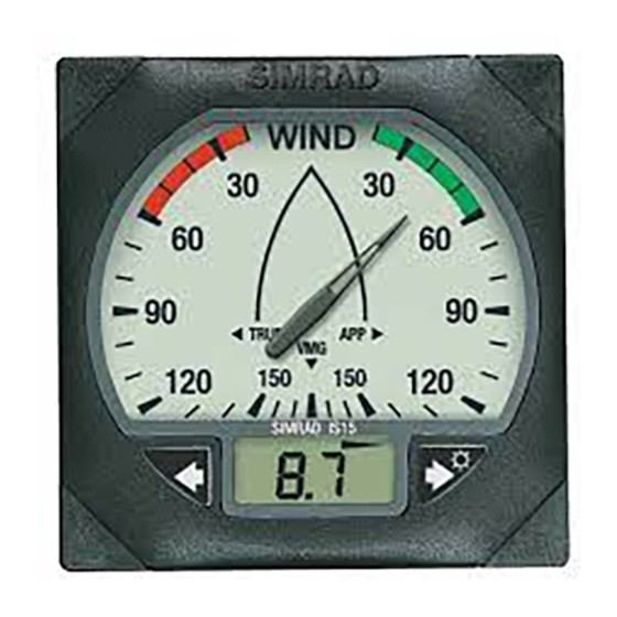
Operation 2 OPERATION OF IS15 WIND INSTRUMENT Scale LCD Arrow legend Pointer Arrow Right button Left button LCD display 2.1 General Description The display is divided into two sections, the scale with pointer, and the LCD. Both are controlled by the two buttons. -
Page 9: Powering Up
IS15 Wind Manual There are three arrows at the top of the LCD indicating what data is being displayed at any one time. The arrow legend is printed on the scale. The right arrow indicates APP for 'Apparent Wind', the left TRUE for 'True Wind', and the center VMG for 'Velocity Made Good'. -
Page 10: Lcd Screens
Operation 2.4 LCD Screens Use short presses on the left/right buttons to select the preferred screen as shown below. Screen Display Screen 1 Screen 2 Screen 3 Screen 4 Screen 5 Analog Apparent True wind Apparent True wind True wind wind angle angle wind angle... - Page 11 IS15 Wind Manual Screen 4 True Wind Angle and VMG This display is indicated by the left LCD arrow being lit, showing 'True' (Wind Angle). Otherwise similar to the Apparent Wind Angle and VMG display. Screen 5 True Wind Angle and Wind Direction...
- Page 12 (alarm on/off) or press and hold for 2 seconds to return to the main screen. Wind Speed Alarm On/Off [A.On – A.OFF] The IS15 Wind display has a true wind speed alarm, and it can be turned on or off as desired. 1. Enter the display damping screen.
-
Page 13: Alarm Sounding
If there is an external alarm connected this will sound at the same time (only if an IS15 Expander is part of the system). To cancel a sounding alarm press any button on any of the instrument heads. - Page 14 Operation True Wind Angle Wind Direction Apparent Wind Angle True Wind Speed Figure 2-2 Apparent / True Wind and Wind Direction 20220752G...
-
Page 15: Operation Of The Is15 Tack
The difference is the magnified wind angle scale which makes it useful when sailing close hauled or running down wind. The operation of IS15 Tack is identical to that of IS15 Wind with the same screen menus on the LCD. Refer to Sections 2 and 6 for further information. -
Page 16: Technical Specifications
Technical Specifications 4 TECHNICAL SPECIFICATIONS 4.1 IS15 WIND (IS15 TACK) True and Apparent Wind Angle Functions Wind Angle Display 0 to 180° (0 to 50° – 130° to 180°) Port / Stbd Wind Angle Resolution 1/3° Wind Angle Damping 4 damping levels (default level 1) - Page 17 C (-22 to +176 30 mm [1,18"] 85 mm Dia [3,35"]. 9 mm (Panel cut-out) [0,35"] 110 mm [4,33"] 21 mm 32 mm [0,83"] [1,26"] Figure 4-1 IS15 Dimensions 600 mm (23.6 in) 178 mm (7 in) Figure 4-2 IS15 Wind Transducer 20220752G...
-
Page 18: Instrument Software Information
• Trip log replaces sea temperature on first screen of IS15 Combi. • In Locked Course mode the LCD on IS15 Compass has been changed to show deviation in degrees from locked course. • Improved log calibration procedure. Possible to set Log reading as percent (%) of default value. - Page 19 IS15 Wind Manual This page is intentionally left blank. 20220752G...
-
Page 20: Installation
This section provides detailed information required to successfully install an IS15 Instrument System utilising the IS15 Wind, IS15 Tack and IS15 Wind Transducer unit. It also describes the connection to peripheral equipment and interconnection with other types of IS15 instruments. - Page 21 IS15 Wind Manual 2. Carefully position the self-adhesive template provided on the surface where the display head is to be mounted. 3. Allow sufficient space for the protection cover as shown on the template when instruments are installed adjacent to each other, see Figure 5-2.
-
Page 22: Wind Transducer
Installation 5.3 Wind Transducer Location The sensor must be mounted in the fore-aft direction, with the sensor forward of the mast so that the wind flow is not affected by the sails. Assembly Counter weight The transducer is supplied with the vane and cups packed separately. -
Page 23: Cabling
Speed/heading (Special) Roblink Power Cable input on NMEA Figure 5-3 W-1 IS15 Wind System Use the Roblink Power Cable (P/N 22093587) for supply to connector no. 1. Cut off one of the plugs on the supplied 0,3 m (1’) cable and extend it to the NMEA source using twisted pair cable. - Page 24 NMEA source via a second instrument. 3. When connected to an IS15 Tri-data system as shown on Figure 5-4 speed is available on Roblink format and heading on NMEA format.
- Page 25 IS15 Wind Manual Figure 5-5 IS15 Instrument system – Cabling diagram 20220752G...
- Page 26 The total length of (Roblink) cables in a system should not exceed 30 m Note ! not including the cable to the Wind Transducer. Refer to section 6.6 in IS15 General Manual. Securing the Cables After the ideal cable routing has been established, use tie-wraps, ‘P’...
-
Page 27: Instrument Head Connections
IS15 Wind Manual Figure 5-6 Securing connectors to the instrument Make sure that all empty sockets have the protection plugs inserted. Coat the connectors with silicone grease or petroleum jelly. These products will not harm the instrument. 5.5 Instrument head connections... - Page 28 Installation NMEA connections general The NMEA port on the IS15 instruments is unidirectional, i.e. it is Note ! automatically configured for input (listening) or output (talking). Thus you will need a minimum of any two instrument heads to make the system both ‘listen’...
- Page 29 Connect the Roblink cable to the NMEA socket on one of the instrument heads. Connect the other end to the screw terminals in the J3xx Junction unit Main Board TX1+ and TX1-. Figure 5-10 Simrad Robertson “X” series autopilot connection 20220752G...
-
Page 30: Wind Transducer Connection
This will provide position and navigation data to the instrument system. Figure 5-11 Simrad XX32/XX40/XX50 series connection Even if the NMEA input is automatically polarized on the IS15 Note ! instruments, it may be necessary to interchange the wires from XX32/40/50 series if depth sounding problems are observed in models that contain a depth sounder. -
Page 31: Is15 Instruments As Nmea Repeaters
Figure 5-12 Wind Transducer Junction Box connections 5.7 IS15 Instruments as NMEA repeaters All IS15 instrument heads can be used as NMEA repeaters either as stand alone units or connected in a “daisy chain” with more heads. Please refer to the IS15 General Manual for detailed information. -
Page 32: Setting-Up
Always turn on all NMEA “listeners” and “talkers” connected to the Note ! system before the first time you turn on the IS15 system. This includes turn on after a COMMUNICATION RESET or a MASTER RESET. The system will then automatically configure the IS15 NMEA ports as talkers or listeners. -
Page 33: Installation And Calibration Menu
IS15 Wind Manual 6.2 Installation and Calibration Menu The installation menu is arranged as follows: Screen Display Screen 1 Screen 2 Screen 3 Screen 4 Analog Apparent wind Apparent wind Apparent wind Apparent wind angle angle angle angle Digital Illumination bank... - Page 34 ILLUM. BANK [bAn.1] The display reads bAn.0 – bAn.2 The IS15 instrument system can have two separate banks of instruments. Setting the lighting level on one display will set all the other displays in that bank to the same level, but will not effect any displays in the other bank.
- Page 35 WIND ANGLE OFFSET – AUTO CALIBRATION [OFS.A] The display reads OFS.A. The IS15 instrument system can be automatically corrected for errors in the mounting of the wind angle sensor. Head the vessel directly into the wind, and then activate the automatic calibration function.
- Page 36 The instrument has a demonstration mode that can be activated by selecting ‘Shop’ On. This function is very useful for dealers when they want to demonstrate the IS15 system or when it is put on display on a show. The Shop Mode is turned off when power is turned off.
- Page 37 IS15 Wind Manual Notes ! 1. The Roblink must be turned Off when the instrument is used as a single NMEA repeater. However, if more heads are daisy-chained as NMEA repeaters the Roblink must be On. 2. When the Roblink has been turned Off it will not default to ON even after a Master Reset.
-
Page 38: Fault Finding
Fault Finding 7 FAULT FINDING If the instrument is part of an IS15 instrument system including a Transceiver (IS15 Power Supply or Expander), or if it is connected to another instrument system as a NMEA repeater, then see the IS15 General Manual. - Page 39 IS15 Wind Manual Wind Display Faults Condition Probable Cause Action There are no Wind The wind transducer Check, and fit the transducer if necessary. Speed or Wind is not fitted to the Check the wind transducer’s Roblink Angle displays, or mast head connector.
- Page 40 Roblink test display The Roblink test display monitors the data flow on the Roblink. On the IS15 Wind and Tack the Roblink test monitors the data utilized by the instrument head, e.g. wind data and compass heading. • Press and hold the button for 10 seconds to enter the installation menu.
-
Page 41: Maintenance
IS15 Wind Manual 8 MAINTENANCE 8.1 General Maintenance Do not use any abrasives, chemical cleaners, petrol or diesel to clean this Caution ! unit. The instrument head will require no maintenance apart from occasional cleaning. Use fresh water and a mild soap solution (not a detergent). -
Page 42: Return For Service
Please ensure that your name, telephone number, return address, a clear fault description, and if possible a copy of the receipt of purchase are included with any returned equipment. Simrad and their representatives are not responsible for any equipment lost in transit. Please quote instrument’s... -
Page 43: Spare Parts List
22092241 IS15 Panel gasket 22092753 IS15 Wind Transducer 22093017 IS15 Wind Transducer PROM (programmed) V..R.. 22092415 IS15 Wind Transducer PCB 44166858 IS15 Wind Transducer Bracket w/30m (100’) cable 44175446 Junction box Roblink Cables 22092019 Roblink Cable 0,3 m 22093728 Roblink Cable 2 m (6,5’) 22092548 Roblink Cable 5 m (16,5’) - Page 44 Fax: +31 181 626688 Fax: +46 31 69 51 20 NORWAY GERMANY CROATIA SWITZERLAND Simrad Marine AS Simrad GmbH & Co. Almar d.o.o. Joh. Berentsensvei 109 Marine Parts Porec - Kamenarija 12 Dithmarscher Strasse 13 P.O. Box 53, Laksevåg Heimgartner...
- Page 45 IS15 Wind Manual SOUTH AFRICA ASIA JAPAN BRAZIL Marine Radio Acoustic Nippon Kaiyo Co, Ltd. Demo Offshore Ltda SINGAPORE Devices 9-2 Sakae-Cho Av. Marechal Camara Jason Electronics Pte P O Box 12076 Kita-Ku Ltd. N1 City 7463 Tokyo 114-0005 Sala 614,...
- Page 46 Manufacturer: Simrad Egersund AS P.O. Box 55 N-4379 Egersund Norway Telephone: +47 51 46 20 00 Telefax: +47 51 46 20 01 www.simrad.com A L W A Y S T H E F O R E F R O N T...
Need help?
Do you have a question about the IS15 and is the answer not in the manual?
Questions and answers