Table of Contents
Advertisement
Quick Links
Advertisement
Table of Contents

Related Manuals for DCS BGA27-BQL


Summary of Contents for DCS BGA27-BQL
- Page 1 This Owner's Manual is provided and hosted by Appliance Factory Parts. DCS BGA27-BQL Owner's Manual Shop genuine replacement parts for DCS BGA27-BQL Find Your DCS Grill Parts - Select From 274 Models -------- Manual continues below part list --------...
- Page 2 Available Replacement Parts for DCS BGA27-BQL 211717 electrode; DCS 214421P RADIANT 214006P CERAMIC ROD (EACH) (9-1/2 INCH rods) 212333P ignition module 210357P ROTISSERIE BURNER FOR DCS 213995 BURNER FOR DCS SS 214119 WARMING RACK (EACH) 211328 HEX BOLT 250072P CONTROL VALVE...
- Page 3 211247 SM 6 X 3/8 PH PN HD TY A SS. 214043 GREASE PAN 214076 ROTIS RECEIVING BRACKET 211242P MS 10-24X1/2 PHPN TY F SS 10PK 214091 FLAVOR TRAY 27D-BQR 212332 BATTERY IGN MODULE 9V 237566 BADGE, 3.3 INCH. 214566 FRONT DOOR PANEL.
- Page 4 THE PROFESSIONAL 27” BGA GRILL Use and Care Guide MODELS: BGA27-BQ BGA27-BQR...
-
Page 5: A Message To Our Customers
A MESSAGE TO OUR CUSTOMERS Thank you for selecting this DCS Professional “BGA” Series Grill. Because of these appliances’ unique features we have developed this Use and Care Guide. It contains valuable information on how to properly operate and maintain your new grill for years of safe and enjoyable cooking. -
Page 6: Table Of Contents
TABLE OF CONTENTS SAFETY PRACTICES & PRECAUTIONS ..........3-5 GRILL MODELS . -
Page 7: Safety Practices & Precautions
SAFETY PRACTICES & PRECAUTIONS IMPORTANT SAFETY NOTICE: Certain Liquid Propane dealers may fill liquid propane cylinders for use in the grill beyond cylinder filling capacity. This “Overfilling” may create a dangerous condition. “Overfilled” tanks can build up excess pressure. As a safety device, the tanks pressure relief valve will vent propane gas vapor to relieve this excess pressure. - Page 8 SAFETY PRACTICES & PRECAUTIONS ■ Never lean over an open grill. When lighting a burner, always pay close attention to what you are doing. Be certain you are pushing the igniter labeled for the burner you intend on using. ■ When using the grill, do not touch the grill rack, burner grate or immediate surrounding area as these areas become extremely hot and could cause burns.
- Page 9 SAFETY PRACTICES & PRECAUTIONS GRILL PLACEMENT EXHAUST VENT FLOW GRILL EXHAUST FLAME PREFERRED AIR FLOW BURNER ■ When using the open top burners always use flat bottomed utensils which are large enough to cover the burner. Adjust the flame so that it heats only the bottom of the pan to avoid ignition of clothing.
-
Page 10: Grill Models
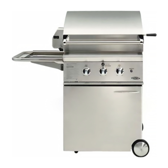
GRILL MODELS BGA27-BQ BGA27-BQR... -
Page 11: Gas Requirements
GAS REQUIREMENTS Verify the type of gas supply to be used, either natural or LP, and make sure the marking on the appliance rating plate agrees with that of the supply. The rating plate is located on the inside back wall of Bottom of unit the Grill. -
Page 12: Lp Tank Requirements
GAS REQUIREMENTS TO HOOK-UP THE FITTINGS SUPPLIED WITH THE GRILL: Assemble as shown (Fig.01). Use threading compound on male threads only. Do not use threading compound on the male end of the 1/2 NPT to 3/8 flare adapter. Use a second pipe wrench to hold the grill inlet pipe to avoid shifting any internal gas lines of the grill. -
Page 13: Locating Grill/Built-In Clearances
Do not build the Grill under unprotected combustible construction. If the Grill is to be placed into a combustible enclosure, an approved insulated jacket is necessary and is available from your dealer. Use only the DCS insulated jacket which has specifically been designed and tested for this purpose. LOCATION: When determining a suitable location take into account concerns such as exposure to wind, proximity to traffic paths and keeping any gas or electrical supply lines as short as possible. -
Page 14: Built-In Grill Clearances
BUILT–IN GRILL CLEARANCES 10" 27-3/4" 6" (minimum for sides (lid) (minimum to with rotisserie side of grill 6" 27-3/4" motor clearance) 34" to non- (to left and (lid) (with rotisserie motor mounted) combustible right side of construction) grill to non- combustible construction) rotisserie... -
Page 15: Built-In Construction Details
BUILT–IN CONSTRUCTION DETAILS 26" grill exhaust 3" (to non-combustible construction / minimum lid clearance) 12" (to combustible construction) 25" 16-1/4" 10-3/8" 22-3/4" 25" Standard layout for non-combustible enclosure: NOTE: If using a backguard apron or rear wall, locate electrical service on the left hand side for rotisserie motor connection 27-3/8"... -
Page 16: Before Testing
LEAK TESTING GENERAL: Although all gas connections on the grill are leak tested at the factory prior to shipment, a complete gas tightness check must be performed at the installation site due to possible mishandling in shipment, or excessive pressure unknowingly being applied to the unit. Periodically check the whole system for leaks, or immediately check if the smell of gas is detected. -
Page 17: Installer Final Checklist
INSTALLER CHECKLIST/BURNER ADJUSTMENTS INSTALLER FINAL CHECKLIST: ❏ Specified clearances main - ❏ Air shutters adjusted. ❏ Unit tested and free of leaks. tained to combustibles. ❏ Adjustable low setting satis- ❏ User informed of gas supply ❏ Nylon straps removed from factory. -
Page 18: Burner Adjustments
BURNER ADJUSTMENTS WARNING: IMPORTANT! Before lighting, inspect the gas supply piping or hose prior to turning the gas "on". If there is evidence of cuts, wear, or abrasion, it must be replaced prior to use. TO ADJUST: 1. Be careful as the burner may be very hot. 2. -
Page 19: Using The Grill
USING THE GRILL GRILL: Each grill section consists of a large stainless steel burner, a series of stainless steel heat baffles, a series of ceramic rods encased in a stainless steel rack, and a stainless steel heat retaining cooking rack. Each burner is rated at 25,000 Btu/hr. -
Page 20: Grilling Hints
USING THE GRILL The Grill is supplied with radiant ceramic rods. Because of the porosity of ceramic rods it is superior in its ability to capture heat as it rises from the grill burners. They also possess the thermal mass needed for results. - Page 21 USING THE GRILL 4. Place the food on the grill and cook to the desired doneness. Adjust heat setting, if necessary. The control knob may be set to any position between “HI” and “LO” . Most grilling is between “MED” and “LO” . 5.
-
Page 22: To Light The Grill Burner
LIGHTING INSTRUCTIONS TO LIGHT THE GRILL BURNER: NOTE: Open the grill cover and/or remove the top grate cover before lighting. Turn all knobs to “OFF” . Turn the main gas supply on. If you smell gas, shut off gas supply and call for service. Push and hold the igniter button, turn the selected burner knob to “HI”... -
Page 23: Using The Rotisserie
USING THE ROTISSERIE BQRN/L MODELS ONLY: The grill rotisserie system is designed to cook items from the back using infrared heat. The location of the burner allows the placement of the rotis basting pan (included) beneath the food to collect juices and drippings for basting and gravy. - Page 24 USING THE ROTISSERIE WARNING: Never have the grill burners ( bottom burners) on during Rotisserie cooking, it will burn your meat and make it very dry. Only one thing on at a time, grill or rotisserie. PREPARATION Recommended: Dental floss or butcher string, scissors, broiler pan (bottom only), pliers, instant read thermometer, foil, and hot pads.
- Page 25 USING THE ROTISSERIE COOKING ON ROTISSERIE 1. Place prepared rod into motor, lay across to other side in groove. (Fig.23) 2. Verify placement as shown in Fig. 24. 3. Ignite Burner, start Rotisserie Motor, and keep on High for cooking all meats on the Rotisserie. 4.
-
Page 26: Manual Lighting
USING THE ROTISSERIE TO LIGHT ROTISSERIE BURNER: All BQR Series Only: The location of the rotis burner makes it more susceptible to strong wind conditions, more so than the protected grill burners. For this reason you should avoid operating the rotis during windy conditions. -
Page 27: Care & Cleaning
CARE AND CLEANING BATTERY REPLACEMENT: 1. Remove grease tray. 2. Open cart door. 3. Pull battery downwards. (This may require use of pliers.) 4. Re-install upward and push to snap - Fig. 29. (Polarity as shown in Fig. 28). FIG. 28 NOTE: Battery condition should be checked at least once a year. -
Page 28: Burner Removal And Cleaning
BURNER REMOVAL AND CLEANING GRILL AND ORIFICE CLEANING: Remove the grill racks, then lift out the grill radiant tray. Grasp the burner, pull it up and slightly to the rear of the unit so the burner head comes off the brass orifice at the front, angle the burner sideways, and remove. -
Page 29: Troubleshooting
You may save the cost of a service call. Troubleshooting is for general purposes only. If the problem persists and you feel you require service, contact your dealer or the nearest authorized agency to perform service. Only authorized agencies can perform warranty service. Call DCS Customer Service at (888) 281-5698. -
Page 30: Grill Burner Assembly / Parts List
GRILL BURNER ASSEMBLY ITEM DESCRIPTION PART NO. ITEM DESCRIPTION PART NO. CONTROL VALVE 13017 GRILL RACK S/S 27 19495-01 CONTROL KNOB 14351 GRILL RACK SS 27 19495-02 KNOB BEZEL 14006-PL RADIANT 32291-02 COLLECTOR BOX 32801 CERAMIC RODS 32224 NI-CHROME WIRE COIL 32313 RADIANT END CAP 32264-01... -
Page 31: Grill Body Parts List
WARMING RACK RET. 27 L/H 32340-01 WARMING RACK RET. 27 R/H 32340-02 LANDING LEDGE W/ASSY. 27 41183 CAGE NUT 15029-02 VALVE PANEL BGA27-BQN 32272-07-PA VALVE PANEL BGA27-BQL 32272-07-PA VALVE PANEL BGA27-BQRN 32272-06-PA VALVE PANEL BGA27-BQRL 32272-06-PA DCS LOGO 17382-01 TORX SCREW 15002-41... -
Page 32: Rotisserie Assembly / Parts List
ROTISSERIE ASSEMBLY ITEM DESCRIPTION PART NO. ITEM DESCRIPTION PART NO. SERVICE PANEL 32269 BOLTS 15150 SCREW 15001-23 THERMOCOUPLE 13007-2 ROTISSERIE BURNER 27DBQR 12021-2 ELECTRODE ROTISSERIE 16282-01 I/R PANEL, 27DBQR 32259 ELECTRODE COVER L/H 32047-01 ROTISSERIE HANDLE 18040 ELECTRODE COVER R/H 32047-02 MEAT HOLDER ASSEMBLY 19010-02... -
Page 33: Grill Cart Parts List
GRILL CART PARTS LIST GRILL CART PARTS LIST DESCRIPTION PART NO. ITEM ITEM DESCRIPTION PART NO. AXLE SPACER 41151-01 FRONT DOOR PANEL 41186 AXLE 41150-01 PULL HANDLE 18204-02 SIDE PANEL R/H 41145-02 SCREW 15002-45 BOTTOM PANEL 41149-01 CATCH BRACKET 14204 TANK RETAINER 41153 HEX NUT... -
Page 34: Wiring Diagram For Bga27-Bq
WIRING DIAGRAM FOR BGA27-BQ #16281-03 #16281-02 #18349 #18353... -
Page 35: Wiring Diagram For Bga27-Bqr
WIRING DIAGRAM FOR BGA27-BQR #16282-01 #16281-02 #16281-03 #18350 #18353... -
Page 36: How To Obtain Service
SERVICE HOW TO OBTAIN SERVICE: For warranty service, contact DCS Customer Service at (888) 281-5698. Before you call, please have the following information ready: ■ Model Number ■ Serial Number ■ Date of installation ■ A brief description of the problem Your satisfaction is of the utmost importance to us. -
Page 37: Warranty
DCS to be defective. Replacement will be F.O.B. DCS, and DCS will not be liable for any transportation costs, labor costs, or export duties. This warranty shall not apply, nor can we assume responsibility for damage that might... - Page 38 5800 Skylab Road, Huntington Beach, CA 92647 Tel: 714.372.7000 • Fax: 714.372.7001 Customer Service: (888) 281.5698 www.dcsappliances.com As product improvement is an ongoing process at DCS, we reserve the right to change specifications or design without notice. Part No. 17556 Rev. D...
Need help?
Do you have a question about the BGA27-BQL and is the answer not in the manual?
Questions and answers