Table of Contents

Related Manuals for DCS BGA26-BQN


Summary of Contents for DCS BGA26-BQN
- Page 1 This Owner's Manual is provided and hosted by Appliance Factory Parts. DCS BGA26-BQN Owner's Manual Shop genuine replacement parts for DCS BGA26-BQN Find Your DCS Grill Parts - Select From 274 Models -------- Manual continues below --------...
- Page 2 THE PROFESSIONAL 26” BGA GRILL Use and Care Guide MODEL: BGA26-BQ...
-
Page 3: A Message To Our Customers
A MESSAGE TO OUR CUSTOMERS Thank you for selecting this DCS Professional “BGA” Series Grill. Because of these appliances’ unique features we have developed this Use and Care Guide. It contains valuable information on how to properly operate and maintain your new grill for years of safe and enjoyable cooking. -
Page 4: Table Of Contents
TABLE OF CONTENTS SAFETY PRACTICES & PRECAUTIONS ..........3-5 GRILL MODEL . -
Page 5: Safety Practices & Precautions
SAFETY PRACTICES & PRECAUTIONS IMPORTANT SAFETY NOTICE: Certain Liquid Propane dealers may fill liquid propane cylinders for use in the grill beyond cylinder filling capacity. This “Overfilling” may create a dangerous condition. “Overfilled” tanks can build up excess pressure. As a safety device, the tanks pressure relief valve will vent propane gas vapor to relieve this excess pressure. - Page 6 SAFETY PRACTICES & PRECAUTIONS ■ Never lean over an open grill. When lighting a burner, always pay close attention to what you are doing. Be certain you are pushing the igniter labeled for the burner you intend on using. ■ When using the grill, do not touch the grill rack, burner grate or immediate surrounding area as these areas become extremely hot and could cause burns.
- Page 7 SAFETY PRACTICES & PRECAUTIONS GRILL PLACEMENT EXHAUST VENT FLOW GRILL EXHAUST FLAME PREFERRED AIR FLOW BURNER ■ Clean the grill with caution. Avoid steam burns; do not use a wet sponge or cloth to clean the grill while it is hot. Some cleaners produce noxious fumes or can ignite if applied to a hot surface.
-
Page 8: Grill Model
GRILL MODEL BGA26-BQ... -
Page 9: Gas Requirements
GAS REQUIREMENTS Verify the type of gas supply to be used, either natural or LP, and make sure the marking on the appliance rating plate agrees with that of the supply. The rating plate is located on the inside back wall of Bottom of unit the Grill. -
Page 10: Lp Tank Requirements
GAS REQUIREMENTS TO HOOK-UP THE FITTINGS SUPPLIED WITH THE GRILL: Assemble as shown (Fig.01). Use threading compound on male threads only. Do not use threading compound on the male end of the 1/2 NPT to 3/8 flare adapter. Use a second pipe wrench to hold the grill inlet pipe to avoid shifting any internal gas lines of the grill. -
Page 11: Locating Grill/Built-In Clearances
Do not build the Grill under unprotected combustible construction. If the Grill is to be placed into a combustible enclosure, an approved insulated jacket is necessary and is available from your dealer. Use only the DCS insulated jacket which has specifically been designed and tested for this purpose. LOCATION: When determining a suitable location take into account concerns such as exposure to wind, proximity to traffic paths and keeping any gas or electrical supply lines as short as possible. -
Page 12: Built-In Grill Clearances
BUILT–IN GRILL CLEARANCES 6" 26-3/4" (lid) (to left and right side of grill to non- combustible construction) 12" combustible construction) 26-3/8" (cutout) 24" grill exhaust 3" (to non- combustible construction / minimum lid clearance) 12" (to combustible construction) 25" 10-3/8" 20-3/4"... -
Page 13: Built-In Construction Details
BUILT–IN CONSTRUCTION DETAILS 24" grill exhaust 3" (to non-combustible construction / minimum lid clearance) 12" (to combustible construction) 25" 18-1/4" 10-3/8" 20-3/4" 23" Standard layout for non-combustible enclosure: NOTE: If using a backguard apron or rear wall, locate electrical service on the left hand side for rotisserie motor connection 26-3/8"... -
Page 14: Before Testing
LEAK TESTING GENERAL: Although all gas connections on the grill are leak tested at the factory prior to shipment, a complete gas tightness check must be performed at the installation site due to possible mishandling in shipment, or excessive pressure unknowingly being applied to the unit. Periodically check the whole system for leaks, or immediately check if the smell of gas is detected. -
Page 15: Installer Final Checklist
INSTALLER CHECKLIST/BURNER ADJUSTMENTS INSTALLER FINAL CHECKLIST: ❏ Specified clearances main - ❏ Air shutters adjusted. ❏ Unit tested and free of leaks. tained to combustibles. ❏ Adjustable low setting satis- ❏ User informed of gas supply ❏ Nylon straps removed from factory. -
Page 16: Burner Adjustments
BURNER ADJUSTMENTS LOW SETTING ADJUSTMENTS: The valves on the grill feature an adjustable low setting. Due to fluctuations in gas pressure, heating value or gas conversion, you may feel it necessary to increase or decrease gas flow in the low position. TO ADJUST: 1. -
Page 17: Using The Grill
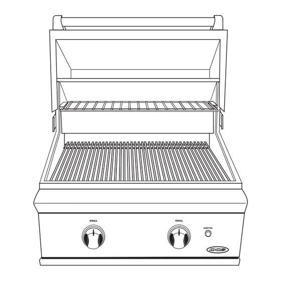
USING THE GRILL GRILL: Each grill section consists of a large stainless steel burner, a series of stainless steel heat baffles, stainless steel radiant, and a stainless steel heat retaining cooking rack. Each burner is rated at 16,500 Btu/hr. Below each burner is a stainless steel heat baffle which reflects usable heat upward into the cooking area and reduces temperatures of the drip pan below. - Page 18 USING THE GRILL 4. Place the food on the grill and cook to the desired doneness. Adjust heat setting, if necessary. The control knob may be set to any position between “HI”and “LO” . Most grilling is between “MED” and “HI” . 5.
-
Page 19: Lighting Instructions
LIGHTING INSTRUCTIONS TO LIGHT THE GRILL BURNER: NOTE: Open the grill lid. Turn all knobs to “OFF” . Turn the main gas supply on. If you smell gas, shut off gas supply and call for service. Push and hold the igniter button, turn the selected burner knob to “HI” . If burner does not light in 4 to 5 seconds turn knob “OFF”... -
Page 20: Care & Cleaning
CARE AND CLEANING BATTERY REPLACEMENT: 1. Remove grease tray. 2. Pull battery downwards. (This may require use of pliers - Fig 13.) 3. Re-install upward and push to snap - Fig 15. (Polarity as shown in Fig. 14). NOTE: Battery condition should be checked at least once a year. FIG. -
Page 21: Burner Removal And Cleaning
BURNER REMOVAL AND CLEANING GRILL AND ORIFICE CLEANING: Remove the grill racks, then lift out the grill radiant tray. Grasp the burner, pull it up and slightly to the rear of the unit so the burner head comes off the brass orifice at the front, angle the burner sideways, and remove. -
Page 22: Troubleshooting
You may save the cost of a service call. Troubleshooting is for general purposes only. If the problem persists and you feel you require service, contact your dealer or the nearest authorized agency to perform service. Only authorized agencies can perform warranty service. Call DCS Customer Service at (888) 281-5698. -
Page 23: Grill Burner Assembly / Parts List
GRILL BURNER ASSEMBLY ITEM DESCRIPTION PART NO. ITEM DESCRIPTION PART NO. CONTROL VALVE 13017 GRILL RACK S/S 26 19498 CONTROL KNOB 14351 RADIANT 33094 KNOB BEZEL 14006-PL 26” HEAT SHIELD, SIDE R/H 33096-01 COLLECTOR BOX 32801 26” HEAT SHIELD, SIDE L/H 33096-02 NI-CHROME WIRE COIL 32313... -
Page 24: Grill Body Parts List
BOLT (SMALL) 15002-36 WARMING RACK RET. 26 L/H 32340-01 WARMING RACK RET. 26 R/H 32340-02 LANDING LEDGE W/ASSY. 26 33129 CAGE NUT 15073 VALVE PANEL BGA26-BQN 33084-PA VALVE PANEL BGA26-BQL 33084-PA DCS LOGO 17382-01 TORX SCREW 15002-41 MATCH LITE, CLIP 32563... -
Page 25: Grill Cart Parts List
GRILL CART PARTS LIST ITEM DESCRIPTION PART NO. SIDE SHELF ASSY 33058 WASHER 15005-15 BOLT 15003-06 FRONT PANEL W/A 33093 SIDE PANEL L/H 33088-02 BACK BRACE 33090 CASTER STIFFENER 33092 CASTER W/BRAKE 18027 CASTER W/O BRAKE 18027-01 SCREW 15002-29 SCREW 15003-06 15021-04 15021-09... -
Page 26: Cart Assembly
CART ASSEMBLY INSTRUCTIONS MOUNT 26” GRILL TO THE CART To install the unit on the cart first remove the drip pan from the grill. Always wear gloves when handling the Professional 26” Gas Grill. Although the unit is deburred prior shipment, some edges may still be sharp enough to cause injury during handling. -
Page 27: Wiring Diagram For Bga26-Bq
WIRING DIAGRAM FOR BGA26-BQ #16281-02 #16281-03 #18350 #18353... -
Page 28: How To Obtain Service
SERVICE HOW TO OBTAIN SERVICE: For warranty service, contact DCS Customer Service at (888) 281-5698. Before you call, please have the following information ready: ■ Model Number ■ Serial Number ■ Date of installation ■ A brief description of the problem Your satisfaction is of the utmost importance to us. -
Page 29: Warranty
DCS to be defective. Replacement will be F.O.B. DCS, and DCS will not be liable for any transportation costs, labor costs, or export duties. This warranty shall not apply, nor can we assume responsibility for damage that might... - Page 30 NOTES...
- Page 31 5800 Skylab Road, Huntington Beach, CA 92647 Tel: 714.372.7000 • Fax: 714.372.7001 Customer Service: (888) 281.5698 www.dcsappliances.com As product improvement is an ongoing process at DCS, we reserve the right to change specifications or design without notice. Part No. 17602 Rev. B...
Need help?
Do you have a question about the BGA26-BQN and is the answer not in the manual?
Questions and answers