TRENDnet TEW 652BRP - Wireless Router User Manual
Ieee 802.11b/g/n wireless home router
Hide thumbs
Also See for TEW 652BRP - Wireless Router:
- User manual (87 pages) ,
- Quick installation manual (20 pages) ,
- Specifications (3 pages)
Table of Contents
Advertisement
Quick Links
Advertisement
Table of Contents

Subscribe to Our Youtube Channel
Related Manuals for TRENDnet TEW 652BRP - Wireless Router


Summary of Contents for TRENDnet TEW 652BRP - Wireless Router
- Page 2 Regulatory notes and statements Wireless LAN, Health and Authorization for use Radio frequency electromagnetic energy is emitted from Wireless LAN devices. The energy levels of these emissions however are far much less than the electromagnetic energy emissions from wireless devices like for example mobile phones.
- Page 3 The availability of some specific channels and/or operational frequency bands are country dependent and are firmware programmed at the factory to match the intended destination. The firmware setting is not accessible by the end user. Europe – EU Declaration of Conformity This device complies with the essential requirements of the R&TTE Directive 1999/5/EC.
- Page 4 Hereby, TRENDnet declares that this TEW-652BRP is in compliance with the essential requirements and English other relevant provisions of Directive 1999/5/EC. Por medio de la presente TRENDnet declara que el TEW-652BRP cumple con los requisitos esenciales y Español [Spanish] cualesquiera otras disposiciones aplicables o exigibles de la Directiva 1999/5/CE.
-
Page 5: Table Of Contents
TABLE OF CONTENT ..................1 BOUT UIDE Purpose ........................................1 Terms/Usage ......................................1 Overview of this User’s Guide .................................. 1 ................... 2 NTRODUCTION Applications: ......................................2 Supported Features: ....................................3 ................4 NPACKING AND ETUP Unpacking ........................................4 Setup ........................................... 4 ................. - Page 6 Routing ........................................39 Static ........................................39 Dynamic ....................................... 40 Routing Table ...................................... 41 Access ........................................42 Filters ........................................42 Virtual Server ....................................... 46 Special AP ......................................47 DMZ ........................................48 Firewall Settings ....................................49 Management ......................................50 Remote Management ................................... 50 Tools .........................................
-
Page 7: About This Guide
ABOUT THIS GUIDE Congratulations on your purchase of this IEEE 802.11b/g/n Wireless Broadband Router. This integrated access device combines Internet gateway functions with wireless LAN and Fast Ethernet switch. It provides a complete solution for Internet surfing and office resource sharing, and it is easy to configure and operate for every user. -
Page 8: Introduction
INTRODUCTION With the explosive growth of the Internet, accessing information and services at any time, day or night has become a standard requirement for most people. The era of the standalone PC is waning. Networking technology is moving out of the exclusive domain of corporations and into homes with at least two computers. -
Page 9: Supported Features
Supported Features: Wi-Fi compliant with IEEE 802.11n and IEEE 802.11b/g standards 4 x 10/100Mbps Auto-MDIX LAN port and 1 x 10/100Mbps WAN port (Internet) Supports Cable/DSL modems with Dynamic IP, Static IP, PPPoE, PPTP, L2TP & BigPond connection types High-speed up to 300Mbps data rate using IEEE 802.11n connection 2 external antennas support high speed performance and great coverage with MIMO technology Firewall features Network Address Translation (NAT), and Stateful Packet... -
Page 10: Unpacking And Setup
UNPACKING AND SETUP This chapter provides unpacking and setup information for the IEEE 802.11b/g/n Wireless Home Router. Unpacking Open the box of the WLAN Router and carefully unpack it. The box should contain the following items: TEW-652BRP Wireless N Home Router CD-Rom (User’s Guide) Multi-Language Quick Installation Guide 2 x 2dBi gain dipole antenna... -
Page 11: Hardware Installation
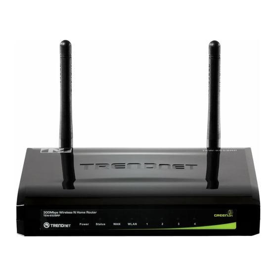
HARDWARE INSTALLATION Front Panel The figure below shows the front panel of the IEEE 802.11b/g/n Wireless Home Router. Front Panel POWER This indicator lights green when the hub is receives power, otherwise it is off. SYSTEM This indicator blinking green means the WLAN Router is working successfully. Otherwise, this indicator always on or off means the function of the WLAN Router has failed. -
Page 12: Rear Panel
Rear Panel The figure below shows the rear panel of the IEEE 802.11b/g/n Wireless Home Router. Rear Panel Antenna There are two 2dBi gain antennas on the rear panel for wireless connection. LAN (1-4) Four RJ-45 10/100Mbps Auto-MDIX ports for connecting to either 10Mbps or 100Mbps Ethernet connections. -
Page 13: Side Panel
Side Panel The figure below shows the side panel of the IEEE 802.11b/g/n Wireless Home Router. WPS (side panel) Push this button to execute the Wi-Fi Protected Setup process. -
Page 14: Hardware Connections
Hardware connections Connecting the WLAN Router 1. Plug in one end of the network cable to the WAN port of the WLAN Router. 2. Plug in the other end of the network cable to the Ethernet port of the xDSL or Cable modem. -
Page 15: Pc Network Tcp/Ip Setting
PC NETWORK TCP/IP SETTING The network TCP/IP settings differ based on the computer’s operating system (Win95/98/ME/NT/2000/XP/Vista) and are as follows. Windows 95/98/ME 1. Click on the “Network neighborhood” icon found on the desktop. 2. Click the right mouse button and a context menu will be show. 3. -
Page 16: Windows 2000
6. Select “None” for the “Gateway address” field. Windows 2000 Double click on the “My Computer” icon on the desktop. When “My Computer” window opens, open the “Control Panel” and then open the “Network dialup connection” applet. Double click on the “Local area network connection” icon. Select “Properties”... -
Page 17: Windows Xp / Vista
Windows XP / Vista Point the cursor and click the right button on the “My Network Place” icon. Select “properties” to enter the TCP/IP setting window. 1. Set “IP address” to “Obtain an IP address automatically.” 2. Set “DNS” to “Obtain DNS server address automatically.”... -
Page 18: Configuration
Before configuring the WLAN Router through WLAN, make sure that the SSID, Channel and the WEP is set properly. The default setting of the WLAN Router that you will use: SSID: TRENDnet Channel: 6 Security: disable Login to the WLAN Router... -
Page 19: Setup Wizard
Setup Wizard Setup wizard is provided as part of the web configuration utility. User can simply follow the step-by-step process to get the wireless Router configuration ready to run in 6 easy steps by clicking on` the “Wizard” button on the function menu. The following screen will appear. - Page 20 Step 3: Set LAN connection and DHCP server Set user’s IP address and mask. The default IP is 192.168.10.1. If the user chooses to enable DHCP, please click “Enable”. DHCP enabled is able to automatically assign IP addresses. Please assign the range of IP addresses in the fields of “Range start”...
- Page 21 Obtain IP automatically (DHCP client): If the user has enabled DHCP server, choose "Obtain IP automatically (DHCP client)" to have the WLAN Router assign IP addresses automatically.
- Page 22 Fixed IP Address: If the Internet Service Provider (ISP) assigns a fixed IP address, choose this option and enter the assigned WAN IP Address, WAN Subnet Mask, WAN Gateway Address and DNS Server Addresses for the WLAN Router.
- Page 23 PPPoE to obtain IP automatically: If connected to the Internet using a PPPoE (Dial-up xDSL) connection, and the ISP provides a User Name and Password, then choose this option and enter the required information.
- Page 24 PPPoE with a fixed IP address: If connected to the Internet using a PPPoE (Dial-up xDSL) connection and the ISP provides a User Name, Password and a Fixed IP Address, choose this option and enter the required information.
- Page 25 PPTP: If connected to the Internet using a PPTP xDSL connection, enter your IP, Subnet Mask, Gateway, Server IP, PPTP Account and PPTP Password.
- Page 26 L2TP: If connected to the Internet using a L2TP (Dial-up xDSL) connection and the ISP provides a Server IP, Account and Password information, choose this option and enter the required information.
- Page 27 Big Pond Cable(Australia): If your ISP is BigPond Cable, the ISP will provide a User Name, Password, Authentication Server and Login Server IP (Optional). Choose this option and enter the required information.
- Page 28 Russia PPPoE: If your ISP is PPPoE in Russia, the ISP will provide a User Name, Password, and Login Server IP. Choose this option and enter the required information.
- Page 29 Russia PPTP: If connected to the Internet using a PPTP (xDSL) connection and the ISP provides a Server IP, Account and Password information, choose this option and enter the required information.
- Page 30 Step 5: Set Wireless LAN connection Click “Enable” to enable Wireless LAN. If user enables the Wireless LAN, type the SSID in the text box and select a communications channel. The SSID and channel must be the same as wireless devices attempting to connect to the WLAN Router. Step 6: Setup completed The Setup wizard is now completed.
-
Page 31: Advanced Configuration
Advanced configuration Main The screen enables users to configure the LAN & DHCP Server, set WAN parameters, create Administrator and User passwords, and set the local time, time zone, and dynamic DNS. LAN & DHCP Server This page allows the user to configure LAN and DHCP properties, such as the host name, IP address, subnet mask, and domain name. -
Page 32: Wan
Start IP: Type an IP address to serve as the start of the IP range that DHCP will use to assign IP addresses to all LAN devices connected to the WLAN Router. End IP: Type an IP address to serve as the end of the IP range that DHCP will use to assign IP addresses to all LAN devices connected to the WLAN Router. -
Page 33: Password
WAN IP: Select whether user wants to specify an IP address manually, or want DHCP to obtain an IP address automatically. When Specify IP is selected, type the IP address, subnet mask, and default gateway in the text boxes. User’s ISP will provide with this information. -
Page 34: Time
Time This screen enables users to set the time and date for the WLAN Router's real-time clock, select properly time zone, and enable or disable daylight saving. Local Time: Displays the local time and date. Time Zone: Select the time zone from the drop-down list. Synchronize the clock with: Select the clock adjustment method form the drop- down list. -
Page 35: Dynamic Dns
Dynamic DNS This synchronizes the DDNS server with your current Public IP address when you are online. First, you need to register your preferred DNS with the DDNS provider. Then, please select the DDNS address in the Server Address and fill the related information in the below fields: Host Name, User Name and Password. -
Page 36: Wireless
Wireless This section enables users to configuration the wireless communications parameters for the WLAN Router. Basic This page allow user to enable and disable the wireless LAN function, create a SSID, and select the channel for wireless communications. Enable/Disable: Enables or disables wireless LAN via the WLAN Router. SSID: Type an SSID in the text box. -
Page 37: Security
Auto 20/40 - Select this option if you are using both 802.11n and non- 802.11n wireless devices. 20MHz – This is the default setting. Select this option if you are not using any 802.11n wireless clients. SSID Broadcast: While SSID Broadcast is enabled, all wireless clients will be able to view the WLAN Router’s SSID. - Page 38 WEP Encryption WEP: Open System and Shared Key requires the user to set a WEP key to exchange data with other wireless clients that have the same WEP key.. Mode: Select the key type: ASCII or HEX WEP Key: Select the level of encryption from the drop-down list. The WLAN Router supports, 64 and 128-bit encryption.
-
Page 39: Advanced
RADIUS Server: 1. Enter the IP address, Port used and Shared Secret by the Primary Radius Server. 2. Enter the IP address, Port used and Shared Secret by the Secondary Radius Server. (optional) WPA-PSK/WPA2-PSK Security If WPA, WPA2 or WPA-Auto PSK is selected. Cipher Type: Select the cipher type for TKIP or AES encryption, Selected Auto for auto detects the cipher type. -
Page 40: Wi-Fi Protected Setup
Beacon Interval: Type the beacon interval in the text box. User can specify a value from 25 to 1000. The default beacon interval is 100. RTS Threshold: Type the RTS (Request-To-Send) threshold in the text box. This value stabilizes data flow. If data flow is irregular, choose values between 256 and 2346 until data flow is normalized. -
Page 41: Status
Push Button Configuration: Clicking the Start PBC button will invoke the Push Button Configuration (PBC) method of WPS. It is only used when WLAN Router acts as a Registrar. Status This selection enables users to view the status of the WLAN Router LAN, WAN and Wireless connections, and view logs and statistics pertaining to connections and packet transfers. -
Page 42: Log
LAN: This section displays the LAN interface configuration including the MAC address, IP Address, Subnet Mask, and DHCP Server Status. Click “DHCP Table” to view a list of client stations currently connected to the WLAN Router LAN interface. Click “DHCP Release” to release all IP addresses assigned to client stations connected to the WAN via the WLAN Router. -
Page 43: Log Setting
Log Setting This screen enables users to set Router Log parameters. SMTP Authentication: Selected the Enabled if the SMTP server need for authentication, fill in account name and password in SMTP Account field and SMTP Password field. SMTP Account: If the SMTP Authentication enabled, fill in the SMTP account name here. -
Page 44: Statistic
Statistic This screen displays a table that shows the rate of packet transmission via the WLAN Router’s LAN, Wireless and WAN ports (in bytes per second). Click “Reset” to erase all statistics and begin logging statistics again. Wireless This screen enables users to view information about wireless devices that are connected to the WLAN Router. -
Page 45: Routing
Routing This selection enables users to set how the WLAN Router forwards data: Static and Dynamic. Routing Table enables users to view the information created by the WLAN Router that displays the network interconnection topology. Static It enables users to set parameters by which the WLAN Router forwards data to its destination if the network has a static IP address. -
Page 46: Dynamic
Dynamic This screen enables users to set the dynamic routing parameters. Transmit: Click the radio buttons to set the desired transmit parameters, Disabled, RIP 1, or RIP 2. Receive: Click the radio buttons to set the desired receive parameters, Disabled, RIP 1, or RIP 2. -
Page 47: Routing Table
Routing Table This screen enables users to view the routing table of the WLAN Router. The routing table is a database created by the WLAN Router that displays the network interconnection topology. Network Address: Displays the network IP address of the connected node. Network Mask: Displays the network (subnet) mask of the connected node. -
Page 48: Access
Access This page enables you to define access restrictions, set up protocol and IP filters, create virtual servers, define access for special applications such as games, and set firewall rules. Filters Using filters to deny or allow the users to access to the internet. Three types of filters can be select: MAC, Domain/URL blocking, and Protocol/IP filter. - Page 49 MAC Filters MAC Filter: Enables you to allow or deny accessing the internet. Disable: Disable the MAC filter function. Allow: Only allow computers with MAC address listed in the MAC Table. Deny: Computers in the MAC Table are denied Internet access. MAC Table: Use this section to create a user profile which internet access is denied or allowed.
- Page 50 Domain/URL Blocking You could specify the domains that allow users to access or deny by clicking one of the two items. Also, add the specified domains in the text box. Disable: Disable the Domain/URL Blocking function. Allow: Allow users to access all domains except “Domains List”. Deny: Deny users to access all domains except “Domains List”.
- Page 51 Protocol/IP Filters This screen enables you to define a minimum and maximum IP address range filter; all IP addresses falling within the range are not allowed accessing internet. The IP filter profiles are listed in the table at the bottom of the page. (Note: Click anywhere in the item.
-
Page 52: Virtual Server
Virtual Server This screen enables user to create a virtual server via the WLAN Router. If the WLAN Router is set as a virtual server, remote users requesting Web or FTP services through the WAN are directed to local servers in the LAN. The WLAN Router redirects the request via the protocol and port numbers to the correct LAN server. -
Page 53: Special Ap
LAN Server: Type the LAN IP address that will be assigned to the virtual server. Add: Click to add the virtual server to the table at the bottom of the screen. Update: Click to update information for the virtual server if the user has selected a listed item and has made changes. -
Page 54: Dmz
Protocol: Select the protocol (TCP, UDP, or * for TCP+UDP) that can be used to access the application. Port Range: Type the port range that can be used to access the application in the text boxes. Incoming: Defines which incoming communications users are permitted to connect with. -
Page 55: Firewall Settings
DMZ Host IP: Type a host IP address for the DMZ. The computer with this IP address acts as a DMZ host with unlimited Internet access. Apply: Click to save the settings. Firewall Settings A firewall protects your network from the outside world, this screen enables users to setup the simple firewall function on the wireless router. -
Page 56: Management
Management Management enables users to set up the Remote Management feature. Remote Management This screen enables users to set up remote management. Using remote management, the WLAN Router can be configured through the WAN via a Web browser. A user name and password are required to perform remote management. -
Page 57: Tools
Tools This page enables users to restart the system, save and load different settings as profiles, restore factory default settings, run a setup wizard to configure WLAN Router settings, upgrade the firmware, and ping remote IP addresses. Restart Click “Restart” to restart the system in the event the system is not performing correctly. -
Page 58: Settings
Settings This screen enables users to save settings as a profile and load profiles for different circumstances. User can also load the factory default settings, and run a setup wizard to configure the WLAN Router and Router interface. Save Settings: Click “Save” to save the current configuration as a profile that can load when necessary. -
Page 59: Firmware
Firmware This screen enables users to keep the WLAN Router firmware up to date. Please follow the below instructions: Download the latest firmware from the manufacturer's Web site, and save it to disk. Click “Browse” and go to the location of the downloaded firmware file. Select the file and click “Upgrade”... -
Page 60: Technical Specifications
TECHNICAL SPECIFICATIONS General Standards IEEE 802.3u 100BASE-TX Fast Ethernet IEEE 802.11n draft 2.0; IEEE 802.11g; IEEE 802.11b Protocol CSMA/CA Radio Technology DSSS/OFDM Data Transfer 802.11n mode: up to 300Mbps (auto sense) Rate 802.11g mode: up to 54Mbps (auto sense) 802.11b mode: up to 11Mbps (auto sense) Ethernet: 10Mbps (half duplex), 20Mbps (full-duplex) Fast Ethernet: 100Mbps (half duplex), 200Mbps (full- duplex) Receiver... -
Page 61: Limited Warranty
3 Years If a product does not operate as warranted above during the applicable warranty period, TRENDnet shall, at its option and expense, repair the defective product or deliver to customer an equivalent product to replace the defective item. All products that are replaced will become the property of TRENDnet.
Need help?
Do you have a question about the TEW 652BRP - Wireless Router and is the answer not in the manual?
Questions and answers