Table of Contents
Advertisement
Quick Links
Advertisement
Table of Contents

Related Manuals for TRENDnet TEW-655BR3G


Summary of Contents for TRENDnet TEW-655BR3G
- Page 1 ...
-
Page 2: Fcc Interference Statement
Copyright ... -
Page 3: Table Of Contents
Table of Contents FCC INTERFERENCE STATEMENT ....................2 INTRODUCTION ........................... 5 Features: ........................5 Wireless Performance Considerations ................ 6 Package List ........................ 7 HARDWARE ..........................7 Front Panel ........................7 Rear Panel ........................8 Side Panel........................8 ... - Page 4 TOOL BOX ..........................42 System Info ....................... 42 Firmware Upgrade ....................43 Backup Setting ......................44 Reset to Default......................44 Reboot ........................45 Miscellaneous ......................45 TROUBLESHOOTING ........................46 SPECIFICATION .......................... 49 ...
-
Page 5: Introduction
Introduction Congratulations on your purchase of this outstanding product: The TEW‐655BR3G 150Mbps Mobile Wireless N Router connects to the Internet either using a traditional hard wired connection or by cutting the cables and connecting with a compatible wireless mobile USB dongle from a 3G* Internet service provider such as AT&T™, T‐Mobile™, or Verizon™**. Designed for true portability the router has a rechargeable and replaceable 2.5 hour lithium ion battery. Compatible with USB dongles from every mobile provider, this compact router connects to the Internet anywhere there is a 3G* mobile connection. No installation is required, simply plug the 3G* USB adapter into the router to share a single Internet connection. The latest wireless encryption protects your valuable data. Wi‐Fi Protected Setup (WPS) integrates other WPS supported clients at the touch of a button. An on/off switch on the back of the devices saves battery life. For long trips, power the router with TRENDnet’s Car Adapter, model TA‐CC. Features: 1 x 10/100Mbps LAN/WAN (optional) port High‐speed data rates up to 150Mbps using an IEEE 802.11n connection*** Works with UMTS/HSPA, WCDMA (HSDPA), CDMA2000 (EV‐DO), and TD‐SCDMA mobile networks 1x USB 2.0 port connects respective third party wireless mobile 3G dongles, from ISPs such as AT&T™, Sprint™, T‐Mobile™, or Verizon™** See the compatibility list on the TEW‐655BR3G product Web page for specific USB modem compatibility Following initial setup, compatible USB modems will be auto‐detected for rapid Internet access Rechargeable and replaceable 2.5 hour lithium Ion battery under full loading and 4 hours in idle mode (Compliant with NP120 type batteries) Built‐in antennas provide high‐speed performance and expansive wireless coverage Advanced Firewall protection with Network Address Translation (NAT) and Stateful Packet Inspection (SPI) Access restriction with Internet Access Control by URL, Domain, packet type, and ... -
Page 6: Wireless Performance Considerations
SNMP V2c support Routing Information Protocol (RIP) table support Easy setup installation wizard with built‐in WAN auto detection *Go to www.trendnet.com for a list of compatible 3G USB modems **Must have an active Internet plan with the respective third party mobile provider ***Maximum wireless signal rates are referenced from IEEE 802.11 theoretical specifications. Actual data throughput and coverage will vary depending on interference, network traffic, building materials, and other conditions. Wireless Performance Considerations There are a number of factors that can impact the range of wireless devices. 1. Adjust your wireless devices so that the signal is traveling in a straight path, rather than at an angle. The more material the signal has to pass through the more signal you will lose. 2. Keep the number of obstructions to a minimum. Each obstruction can reduce the range of a wireless device. Position the wireless devices in a manner that will minimize the amount of obstructions between them. 3. Building materials can have a large impact on your wireless signal. In an indoor environment, try to position the wireless devices so that the signal passes through less dense material such as dry wall. Dense materials like metal, solid wood, glass or even furniture may block or degrade the signal. 4. Antenna orientation can also have a large impact on your wireless signal. Use the wireless adapter’s site survey tool to determine the best antenna orientation for your wireless devices. 5. Interference from devices that produce RF (radio frequency) noise can also impact ... -
Page 7: Package List
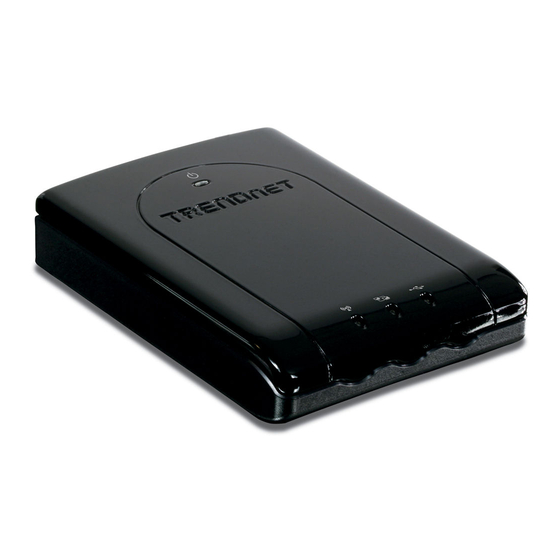
Package List TEW‐6555BR3G The 150Mbps Mobile Wireless N Router Multi‐Language Quick Installation Guide CD‐ROM (User’s Guide) Cat. 5 Ethernet cable (1m/3.2ft) Power Adapter 5V, 2A Battery 3.7V, 1700mAh Hardware Front Panel The figure below shows the front panel of the 150Mbps Mobile Wireless N Router. Front Panel POWER This indicator lights green when the unit is receives power and the battery is charging. The indicator lights red with the unit is on and the battery is low. Ethernet (Link/ACT) This indicator light green when a device is connected to Ethernet port. The indicators blink green during data transmission. 3G/WLAN (ACT) This indicator lights green when there are wireless device is active. The indicator flashes during data transmission. ... -
Page 8: Rear Panel
Rear Panel The figure below shows the rear panel of the 150Mbps Mobile Wireless N Router. Rear Panel LAN/WAN (optional) One RJ‐45 10/100Mbps Auto‐MDIX ports for connecting to either 10Mbps or 100Mbps Ethernet connections. POWER Switch Switch to turn off/on the device. POWER Plug the power adapter to this power jack Side Panel The figure below shows the side panel of the 150Mbps Mobile Wireless N Router. Side Panel WPS Push this button to execute the Wi‐Fi Protected Setup process. RESET Use a pin‐shaped item to push to reset this device to factory default settings. It will be a useful tool when the manager forgot the password to login, and needs to restore the device back to default settings. ... -
Page 9: Getting Started
Getting Started Installation Please make sure that Step 1. Verify that you have an Internet connection when connecting the 3G USB adapter to your computer.. Open your browser (e.g. Internet Explorer) and type in a URL (e.g. http://www.trendnet.com) in the addres s ar. Note: You may need to activate your Internet connection. P lease contact your ISP for more formation. DO NOT insert or remove the Li‐ion battery while the p ower witch is at ON position. Step 2. Remove the battery lid located on the ... - Page 10 Step 5. Power ON: Move the Power switch to the on position. Step 6. Connect with a USB 3G modem: Connect your 3G USB adapter to the USB port on the TEW‐655BR3G. ...
-
Page 11: Configure With The Setup Wizard
Configure with the Setup Wizard Type in the IP Address (http://192.168.10.1) Type in the default password “admin” in the System Password and then click ‘login’ button. Click “Wizard” on the top of the screen. Press “Next” to start the Setup Wizard. Step 1: Change System Password. Set up your system password. (Default:admin) ... - Page 12 Step 2: Select Time Zone. Step 3: Select Wan Type. If you want to use 3G service as the main internet access, please set the WAN interface as “Wireless WAN” and the WAN type as “3G”. Step 4: Set up 3G profile. Select “Auto Detection”. Step 5: Set up your Wireless Network. Set up your SSID. ...
- Page 13 Step 6: Set up Wireless Security. Set up your Authentication and Encryption. Step 7: Apply your Setting. Then click “Apply Setting”. Step 8: Click “Finish” to complete it. ...
-
Page 14: Advance Configuration
Advance Configuration Whenever you want to configure the device, you can access the Configuration Menu by opening a web‐browser and typing in the IP Address of the device. The default IP Address is: 192.168.10.1 Enter the default password “admin” in the System Password and then click the ‘login’ button. Click “Advanced” option on the top of the screen to enter the advance configuration of the device. Basic Setting This section enables users to configure the basic settings like WAN and LAN parameters, Wireless settings including wireless encryption and the unit’s Password. ... -
Page 15: Network Setup
Network Setup Ethernet port Configuration: Off: Disable the Ethernet port. LAN: Set the Ethernet port as LAN port. WAN: Set the Ethernet port as WAN port. Auto: When selected the Ethernet port detects for WAN (Internet) DHCP, if no DHCP is detected the Ethernet port automatically turns into a LAN port. LAN IP Address: The local IP address of this device. The computers on your network must use the LAN IP address of this device as their Default Router. You can change it if necessary. Default LAN IP is 192.168.10.1 Subnet Mask: Input your Subnet mask. (All devices in the network must have the same subnet mask.) The default subnet mask is 255.255.255.0. WAN Interface: Select Ethernet WAN or Wireless WAN to continue. WAN Type: WAN connection type of your ISP. You can click WAN Type combo button to choose a correct one from the following options: ... - Page 16 For 3G WAN Networking. The WAN fields may not be necessary for your connection. The information on this page will only be used when your service provider requires you to enter a User Name and Password to connect with the 3G network. Please refer to your 3G documentation or service provider for additional information. Dial‐Up Profile: Select “Auto‐Detection” or “Manual” to continue. If “Auto‐Detection” is selected, the device will try to configure some ISP specific dial‐up parameters automatically according to the Country, Telecom, and 3G Network information you entered.. Country: Select your country. Telecom: Select your telecom. 3G Network: Select the 3G Network APN: Enter the APN for your PC card here.(Optional) Pin Code: Enter the Pin Code for your SIM card. (Optional) Dial‐Number: This field should not be altered except when required by your service provider. ...
-
Page 17: Static Ip Address
Secondary DNS: This feature allows you to assign a Secondary DNS Server, you can contact to your ISP to get it. (Optional) Connection Control: Select your connection control. There are 3 modes to select: Connect‐on‐demand: The device will link up with ISP when the clients send outgoing packets. Auto Reconnect (Always‐on): The device will link with ISP until the connection is established. Manually: The device will not make the link until someone clicks the connect‐button in the Status‐page. Keep Alive: This feature must collocate with the function "Auto" of "Auto Connect". Enable it to keep the connection always be established. LCP Echo Request: Enter the time interval and the maximum failure count. The device will constantly send out the LCP packets for keeping the connection alive. Ping Remote Host: Enter the Remote host IP and the time interval to send the ping packets for keeping the connection alive. ... -
Page 18: Dynamic Ip Address
Dynamic IP Address: Activate WWAN for Auto‐Failover: With this function enabled, when the Ethernet WAN connection is broken, the device will automatically activate the WWAN connection and keep you connected to internet with the alternative WWAN broadband service. Meanwhile, if the device detected that the Ethernet WAN connection is recovered, your broadband connection will be switched to use the Ethernet WAN service Host Name: Optional, required by some ISPs, for example, @Home. Connection Control: There are 3 modes to select: Connect‐on‐demand: The device will link up with ISP when the clients send outgoing packets. Auto Reconnect (Always‐on): The device will link with ISP until the connection is established. Manually: The device will not make the link until someone clicks the connect‐button in the Status‐page. PPP over Ethernet ... -
Page 19: Pptp
Activate WWAN for Auto‐Failover: With this function enabled, when the Ethernet WAN connection is broken, the device will automatically activate the WWAN connection and keep you connected to internet with the alternative WWAN broadband service. Meanwhile, if the device detected that the Ethernet WAN connection is recovered, your broadband connection will be switched to use the Ethernet WAN service PPPoE Account and Password: The account and password your ISP assigned to you. For security, this field appears blank. If you don't want to change the password, leave it blank. Connection Control: There are 3 modes to select: Connect‐on‐demand: The device will link up with ISP when the clients send outgoing packets. Auto Reconnect (Always‐on): The device will link with ISP until the connection is established. ... -
Page 20: L2Tp
broadband connection will be switched to use the Ethernet WAN service IP Mode: Please check the IP mode your ISP assigned, and select “Static IP Address” or “Dynamic IP Address”. My IP Address and My Subnet Mask: The private IP address and subnet mask your ISP assigned to you. Router IP and Server IP Address/Name: The IP address of the PPTP server and designated Router provided by your ISP. PPTP Account and Password: The account and password your ISP assigned to you. If you don't want to change the password, keep it blank. Connection ID: Optional. Input the connection ID if your ISP requires it. Maximum Idle Time: the time of no activity to disconnect your PPTP session. Set it to zero or enable “Auto‐reconnect” to disable this feature. If Auto‐reconnect is enabled, this device will connect with ISP automatically after system is restarted or connection is ... -
Page 21: Dhcp Server
Meanwhile, if the device detected that the Ethernet WAN connection is recovered, your broadband connection will be switched to use the Ethernet WAN service IP Mode: Please check the IP mode your ISP assigned, and select “Static IP Address” or “Dynamic IP Address”. My IP Address and My Subnet Mask: The private IP address and subnet mask your ISP assigned to you. Router IP and Server IP Address/Name: The IP address of the L2TP server and designated Router provided by your ISP. L2TP Account and Password: The account and password your ISP assigned to you. If you don't want to change the password, keep it blank. Connection ID: Optional. Input the connection ID if your ISP requires it. Maximum Idle Time: The time of no activity to disconnect your L2TP session. Set it to zero or enable “Auto‐reconnect” to disable this feature. If Auto‐reconnect is enabled, this device will connect with ISP automatically, after system is restarted or connection is ... - Page 22 Press “More>>” and you can find more settings Primary DNS/Secondary DNS: Optional. This feature allows you to assign a DNS Servers Primary WINS/Secondary WINS: Optional. This feature allows you to assign a WINS Servers Router: Optional. Router Address would be the IP address of an alternate Router. This function enables you to assign another Router to your PC, when DHCP server offers an IP to your PC. Click on “Save” to store your settings or click “Undo” to reset changes. Press “Clients List” and the list of DHCP clients will be shown. Press “Fixed Mapping” and the DHCP Server will reserve the special IP for designated MAC address. ...
-
Page 23: Wireless Settings
Wireless Settings This section allows users to configure all wireless settings of the router. Allows you to set the wireless configuration items. Wireless Module: You can enable or disable wireless function. Network ID (SSID): Network ID is used for identifying the Wireless LAN (WLAN). Client stations can roam freely over this device and other Access Points that have the same Network ID. (The factory default setting is “default”) SSID Broadcast: The router will broadcast beacons that have some information, including SSID so that wireless clients can know how many AP devices by scanning the network. Therefore, if this setting is configured as “Disable”, the wireless clients can not find the device from beacons. Channel: The radio channel number. The permissible channels depend on the Regulatory Domain. The factory default setting is as follow: channel 1~11 for North America. (Channel 1~13 for European (ETSI); channel1~ 14 for Japan). ... - Page 24 authentication process have the same "shared" key or passphrase. The shared key is manually set on both the client station and the AP/router. Three types of shared key authentication are available today for home or small office WLAN environments. Auto The AP will Select the Open or Shared by the client’s request automatically. WPA‐PSK Select Encryption and Pre‐share Key Mode If you select HEX, you have to fill in 64 hexadecimal (0, 1, 2…8, 9, A, B…F) digits. If you select ASCII, the length of pre‐share key is from 8 to 63. Fill in the key, Ex 12345678 WPA Check Box was used to switch the function of the WPA. When the WPA function is enabled, the Wireless user must authenticate to this router first to use the Network service. RADIUS Server IP address or the 802.1X server’s domain‐name. Select Encryption and RADIUS Shared Key If you select HEX, you have to fill in 64 hexadecimal (0, 1, 2…8, 9, A, B…F) digits If you select ASCII, the length of pre‐share key is from 8 to 63. Key value shared by the RADIUS server and this router. This key value is consistent with the key value in the RADIUS server. ...
-
Page 25: Change Password
WPS: You can enable this function by selecting “Enable”. WPS offers a safe and easy way to allow the wireless clients connected to your wireless network. AP PIN: You can press Generate New Pin to get an AP PIN. Config Mode: Select your config Mode from “Registrar” or “Enrollee”. Config Status: It shows the status of your configuration. Config Method: You can select the Config Method here from “Pin Code” or “Push Button”. WPS status: According to your setting, the status will show “Start Process” or “No used” Press “Wireless Clients List” and the list of wireless clients will be shown consequently. Change Password You can change the System Password here. We strongly recommend you to change the system password for security reason. Click on “Save” to store your settings or click “Undo” to give up the changes. ... -
Page 26: Forwarding Rules
Forwarding Rules This section defines access restrictions, set up protocol and IP filters, create virtual server rules and special applications rules and DMZ (Demilitarized Zone). Please note that certain 3G network providers issues virtual WAN IP addresses causing these features not to work. Contact your 3G network service provider for additional information. Virtual Server This product’s NAT firewall filters out unrecognized packets to protect your Intranet, so all hosts behind this product are invisible to the outside world. If you wish, you can make some of them accessible by enabling the Virtual Server Mapping. A virtual server is defined as a Service Port, and all requests to this port will be redirected to the computer specified by the Server IP. Virtual Server can work with Scheduling Rules, and give user more flexibility on Access control. For the details, please ... -
Page 27: Special Ap
For example, if you have an FTP server (port 21) at 192.168.123.1, a Web server (port 80) at 192.168.123.2, and a VPN server at 192.168.123.6, then you need to specify the following virtual server mapping table: Service Port Server IP Enable 21 192.168.123.1 V 80 192.168.123.2 V 1723 192.168.123.6 V Click on “Save” to store your settings or click “Undo” to give up the changes. Special AP Some applications require multiple connections, like Internet games, Video conferencing, Internet telephony, etc. Because of the firewall function, these applications cannot work with a pure NAT router. The Special Applications feature allows some of these applications to work with this product. If the mechanism of Special Applications fails to ... -
Page 28: Miscellaneous
Trigger: The outbound port number issued by the application. Incoming Ports: When the trigger packet is detected, the inbound packets sent to the specified port numbers are allowed to pass through the firewall.This device provides some predefined settings. Select your application and click “Copy to” to add the predefined setting to your list. ... -
Page 29: Security Setting
Security Setting Packet Filters Packet Filter includes both outbound filter and inbound filter. And they have same way to setting. Packet Filter enables you to control what packets are allowed to pass the router. Outbound filter applies on all outbound packets. However, inbound filter applies on packets that destined to Virtual Servers or DMZ host only. You can select one of the two filtering policies: Allow all to pass except those match the specified rules Deny all to pass except those match the specified rules ... - Page 30 You can specify 8 rules for each direction: inbound or outbound. For each rule, you can define the following: • Source IP address • Source port • Destination IP address • Destination port • Protocol: TCP or UDP or both. • Use Rule# For source or destination IP address, you can define a single IP address (4.3.2.1) or a range of IP addresses (4.3.2.1‐4.3.2.254). An empty implies all IP addresses. For source or destination port, you can define a single port (80) or a range of ports (1000‐1999). ...
-
Page 31: Domain Filters
Domain Filters Domain Filter prevents users under this device from accessing specific URLs. Domain Filter: Check if you want to enable Domain Filter. Log DNS Query: Check if you want to log the action when someone accesses the specific URLs. Privilege IP Address Range: Setting a group of hosts and privilege these hosts to access network without restriction. Domain Suffix: A suffix of URL can be restricted, for example, ".com", "xxx.com". Action: When someone is accessing the URL met the domain‐suffix, what kind of action you want. Check “Drop” to block the access. Check “Log” to log this access. Enable: Check to enable each rule. Click on “Save” to store your settings or click “Undo” to give up the changes. ... -
Page 32: Url Blocking
URL Blocking URL Blocking will block LAN computers to connect with pre‐define Websites. The major difference between “Domain filter” and “URL Blocking” is Domain filter require user to input suffix (like .com or .org, etc), while URL Blocking require user to input a keyword only. In other words, Domain filter can block specific website, while URL Blocking can block hundreds of websites by simply a keyword. URL Blocking: Check if you want to enable URL Blocking. URL: If any part of the Website's URL matches the pre‐defined word, the connection will be blocked. For example, you can use pre‐defined word "sex" to block all websites if their URLs contain pre‐defined word "sex". ... -
Page 33: Mac Control
MAC Control MAC Address Control allows you to assign different access right for different users and to assign a specific IP address to a certain MAC address. MAC Address Control: Check “Enable” to enable the “MAC Address Control”. All of the settings in this page will take effect only when “Enable” is checked. Connection control: Check "Connection control" to enable the controlling of which wired and wireless clients can connect with this device. If a client is denied to connect with this device, it means the client can't access to the Internet either. Choose "allow" or "deny" to allow or deny the clients, whose MAC addresses are not in the "Control table" (please see below), to connect with this device. Association control: Check "Association control" to enable the controlling of which wireless client can associate to the wireless LAN. If a client is denied to associate to the wireless LAN, it means the client can't send or receive any data via this device. Choose "allow" ... -
Page 34: Miscellaneous
Miscellaneous Administrator Time‐out: The time of no activity to logout automatically, you may set it to zero to disable this feature. Remote Administrator Host/Port In general, only Intranet user can browse the built‐in web pages to perform administration task. This feature enables you to perform administration task from remote host. If this feature is enabled, only the specified IP address can perform remote administration. If the specified IP address is 0.0.0.0, any host can connect with this product to perform administration task. You can use subnet mask bits "/nn" notation to ... -
Page 35: Advanced Setting
Advanced Setting System Log This page support two methods to export system logs to specific destination by means of syslog (UDP) and SMTP(TCP). The items you have to setup including: IP Address for Sys log: Host IP of destination where sys log will be sent to. Check Enable to enable this function. E‐mail Alert Enable: Check if you want to enable Email alert (send syslog via email). SMTP Server IP and Port: Input the SMTP server IP and port, which are connected with ... -
Page 36: Dynamic Dns
':'. If you do not specify port number, the default value is 25. For example, "mail.your_url.com" or "192.168.1.100:26". Send E‐mail alert to: The recipients who will receive these logs, you can assign more than 1 recipient, using ';' or ',' to separate these email addresses. E‐mail Subject: The subject of email alert, this setting is optional. Click on “Save” to store your settings or click “Undo” to give up the changes. Dynamic DNS To host your server on a changing IP address, you have to use dynamic domain name service (DDNS). So that anyone wishing to reach your host only needs to know the name of it. Dynamic DNS will map the name of your host to your current IP address, which changes each time you connect your Internet service provider. Before you enable Dynamic DNS, you need to register an account on one of these Dynamic DNS servers that we list in Provider field. Please note that certain 3G network providers issues virtual WAN IP addresses causing this feature not to work. Contact your 3G network service provider for additional information. To enable Dynamic DNS click the check box next to Enable in the DDNS field. Next you have to enter the appropriate information about your Dynamic DNS Serve .Provider, ... -
Page 37: Qos
QoS Provide different priority to different users or data flows, or guarantee a certain level of performance. QoS Control: Check Enable to enable this function. Bandwidth of Upstream: Set the limitation of upstream bandwidth Local IP : Ports: Define the Local IP address and ports of packets Remote IP : Ports: Define the Remote IP address and ports of packets QoS Priority: This defines the priority level of the current Policy Configuration. Packets associated with this policy will be serviced based upon the priority level set. For critical applications High or Normal level is recommended. For non‐critical applications select a Low level. Enable: Check to enable the corresponding QOS rule. User Rule#: The QoS rule can work with Scheduling Rule number#. Please refer to the Section 3.1.4.7 Schedule Rule. Click on “Save” to store your settings or click “Undo” to give up the changes. ... -
Page 38: Snmp
SNMP In brief, SNMP, the Simple Network Management Protocol, is a protocol designed to give a user the capability to remotely manage a computer network by polling and setting terminal values and monitoring network events. Enable SNMP: You must check “Local”, “Remote” or both to enable SNMP function. If “Local” is checked, this device will response request from LAN. If “Remote” is checked, this device will response request from WAN. Get Community: The community of GetRequest that this device will respond. Set Community: The community of SetRequest that this device will accept. IP 1, IP 2, IP 3, IP 4: Enter the IP addresses of your SNMP Management PCs. User has to configure to where this device should send SNMP Trap message. SNMP Version: Select proper SNMP Version that your SNMP Management software supports. WAN ... -
Page 39: Routing
Routing If you have more than one routers and subnets, you will need to enable routing table to allow packets to find proper routing path and allow different subnets to communicate with each other. The routing table allows you to determine which physical interface address to use for outgoing IP data grams. Dynamic Routing: Routing Information Protocol (RIP) will exchange information about destinations ... -
Page 40: System Time
System Time Time Zone: Select a time zone where this device locates. Auto‐Synchronization: Check the “Enable” checkbox to enable this function. Besides, you can select a NTP time server to consult UTC time. Sync with Time Server: Click on the button if you want to set Date and Time by NTP Protocol manually. Sync with my PC: Click on the button if you want to set Date and Time using PC’s Date and Time manually. Click on “Save” to store your settings or click “Undo” to give up the changes. Scheduling ... - Page 41 Schedule: Check to enable the schedule rule settings. Add New Rule: To create a schedule rule, click the “Add New Rule” button. You can edit the Name of Rule, Policy, and set the schedule time (Week day, Start Time, and End Time). The following example configures “ftp time” as everyday 14:10 to 16:20. Click on “Save” to store your settings or click “Undo” to give up the changes. ...
-
Page 42: Tool Box
Tool Box System Info You can view the System Information and System log, and download/clear the System log, in this page. ... -
Page 43: Firmware Upgrade
Firmware Upgrade You can upgrade firmware by clicking “Upgrade” button. ... -
Page 44: Backup Setting
Backup Setting You can backup your settings by clicking the “Backup Setting” function item and save it as a bin file. Once you want to restore these settings, please click Firmware Upgrade button and use the bin file you saved. You can backup your settings by clicking the “Backup Setting” function item and save it as a bin file. Once you want to restore these settings, please click Firmware Upgrade button and use the bin file you saved. Reset to Default ... -
Page 45: Reboot
Reboot You can also reboot this device by clicking the Reboot function item. Miscellaneous Domain Name or IP address for Ping Test: Allow you to configure an IP, and ping the device. You can ping a specific IP to test whether it is alive. Click on “Save” to store your settings or click “Undo” to give up the changes. ... -
Page 46: Troubleshooting
Troubleshooting This Chapter provides solutions to problems for the installation and operation of the The 150Mbps Mobile Wireless N Router. You can refer to the following if you are having problems. 1 Why can’t I configure the router even the cable is plugged and the LED is lit? Do a Ping test to make sure that The 150Mbps Mobile Wireless N Router is properly working and responding. Note: It is recommended that you use an Ethernet connection to configure it Go to Start > Run. 1. Type cmd. 2. Press OK. 3. - Page 47 2 What can I do if my Ethernet connection does not work properly? A. Make sure the RJ45 cable connect with the router. B. Ensure that the setting on your Network Interface Card adapter is “Enabled”. C. If settings are correct, ensure that you are not using a crossover Ethernet cable, not all Network Interface Cards are MDI/MDIX compatible, and use a patch cable is recommended. D. If the connection still doesn’t work properly, then you can reset it to default. 3 Problems with 3G connection? A. What can I do if the 3G connection is failed by Auto detection? Maybe the device can’t recognize your ISP automatically. Please select “Manual” mode, and filling in dial‐up settings manually. B. What can I do if my country and ISP are not in the list? Please choose “Others” item from the list, and filling in dial‐up settings manually. C.
- Page 48 entered for the network. VII. If you are using other wireless device, home security systems or ceiling fans, lights in your home, your wireless connection may degrade dramatically. Keep your product away from electrical devices that generate RF noise such as microwaves, monitors, electric motors… B. What can I do if my wireless client can not access the Internet? I. Out of range: Put the router closer to your client. II. Wrong SSID or Encryption Key: Check the SSID or Encryption setting. III. Connect with wrong AP: Ensure that the client is connected with the correct Access Point. Right‐click on the Local Area Connection icon in the taskbar. Select View Available Wireless Networks in Wireless Configure. Ensure you have selected the correct available network. iii. Reset the WiFi Mobile Router to default setting C. Why does my wireless connection keep dropping? I. Antenna Orientation. i.Try different antenna orientations for the WiFi Mobile Router. ii.Try to keep the antenna at least 6 inches away from the wall or other objects. II. Try changing the channel on the WiFi Mobile Router, and your Access Point and Wireless adapter to a different channel to avoid interference. ...
-
Page 49: Specification
Wired: IEEE 802.3 (10Base‐T), IEEE 802.3u (100Base‐TX) Standards Wireless: IEEE 802.11b, IEEE 802.11g, IEEE 802.11n USB: USB 2.0, USB 1.1 USB Port 1 x USB 2.0 port for 3G USB adapter (Internet) Ethernet Port 1 x 10/100Mbps Auto‐MDIX port (LAN/Internet) Ethernet: Dynamic IP, Static IP, PPPoE, L2TP, PPtP WAN Connection Type USB: 3G, 3.75G Compatible 3G/3.75G UMTS/HSPA, WCDMA (HSDPA), CDMA2000 (EV‐DO) & Mobile Networks TD‐SCDMA Compatible Carriers in USA AT&T, Verizon, T‐Mobile **** (need to write disclaimer) Compatible USB Adapters Visit www.trendnet.com for a list of compatible USB adapters NAT, NAPT and SPI Static / Dynamic Route (RIP v1/v2) UPnP, DMZ, Static/Dynamic Route support Router/ Firewall DoS (blocking ping, port scan, sync flood) MAC, port range, service, domain and URL filtering (deny or allow) and ICMP blocking Power Switch Slide On/Off WPS Button Wi‐Fi Protected Setup (WPS) with other WPS compliant devices Battery 3.7V, 1700MAh Li‐ION battery (Compliant to NP120) LED Indicator Power, Wireless/WPS, USB (3G adapter), Ethernet (WAN/LAN) Power Adapter ... - Page 50 802.11n: ‐68dBm @ 150Mbos Channels 1~11 (FCC), 1~13 (ETSI) ...
-
Page 51: Limited Warranty
Limited Warranty TRENDnet warrants its products against defects in material and workmanship, under normal use and service, for the following lengths of time from the date of purchase. TEW‐655BR3G – 3 Years Warranty AC/DC Power Adapter, Cooling Fan, and Power Supply carry 1 year warranty. If a product does not operate as warranted during the applicable warranty period, TRENDnet shall reserve the right, at its expense, to repair or replace the defective product or part and deliver an equivalent product or part to the customer. The repair/replacement unit’s warranty continues from the original date of purchase. All products that are replaced become the property of TRENDnet. Replacement products may be new or reconditioned. TRENDnet does not issue refunds or credit. Please contact the point‐of‐purchase for their return policies. TRENDnet shall not be responsible for any software, firmware, information, or memory data of customer contained in, stored on, or integrated with any products returned to TRENDnet pursuant to any warranty. There are no user serviceable parts inside the product. Do not remove or attempt to service the product by any unauthorized service center. This warranty is voided if (i) the product has been modified or repaired by any unauthorized service center, (ii) the product was subject to accident, abuse, or improper use (iii) the product was subject to conditions more severe than those specified in the manual. Warranty service may be obtained by contacting TRENDnet within the applicable warranty period and providing a copy of the dated proof of the purchase. Upon proper ... - Page 52 IT ANY OTHER LIABILITY IN CONNECTION WITH THE SALE, INSTALLATION MAINTENANCE OR USE OF TRENDNET’S PRODUCTS. TRENDNET SHALL NOT BE LIABLE UNDER THIS WARRANTY IF ITS TESTING AND EXAMINATION DISCLOSE THAT THE ALLEGED DEFECT IN THE PRODUCT DOES NOT EXIST OR WAS CAUSED BY CUSTOMER’S OR ANY THIRD PERSON’S MISUSE, NEGLECT, IMPROPER INSTALLATION OR TESTING, UNAUTHORIZED ATTEMPTS TO REPAIR OR MODIFY, OR ANY OTHER CAUSE BEYOND THE RANGE OF THE INTENDED USE, OR BY ACCIDENT, FIRE, LIGHTNING, OR OTHER HAZARD. LIMITATION OF LIABILITY: TO THE FULL EXTENT ALLOWED BY LAW TRENDNET ALSO EXCLUDES FOR ITSELF AND ITS SUPPLIERS ANY LIABILITY, WHETHER BASED IN CONTRACT OR TORT (INCLUDING NEGLIGENCE), FOR INCIDENTAL, CONSEQUENTIAL, INDIRECT, SPECIAL, OR PUNITIVE DAMAGES OF ANY KIND, OR FOR LOSS OF REVENUE OR PROFITS, LOSS OF BUSINESS, LOSS OF INFORMATION OR DATE, OR OTHER FINANCIAL LOSS ARISING OUT OF OR IN CONNECTION WITH THE SALE, INSTALLATION, MAINTENANCE, USE, PERFORMANCE, FAILURE, OR INTERRUPTION OF THE POSSIBILITY OF SUCH DAMAGES, AND LIMITS ITS LIABILITY TO REPAIR, REPLACEMENT, OR REFUND OF THE PURCHASE PRICE PAID, AT TRENDNET’S OPTION. THIS DISCLAIMER OF LIABILITY FOR DAMAGES WILL NOT BE AFFECTED IF ANY REMEDY PROVIDED HEREIN SHALL FAIL OF ITS ESSENTIAL PURPOSE. Governing Law: This Limited Warranty shall be governed by the laws of the state of California. Some TRENDnet products include software code written by third party developers. These codes are subject to the GNU General Public License ("GPL") or GNU Lesser General Public License ("LGPL"). Go to http://www.trendnet.com/gpl or http://www.trendnet.com Download section and look for the desired TRENDnet product to access to the GPL Code or LGPL Code. These codes are distributed WITHOUT WARRANTY and are subject to the copyrights of the developers. TRENDnet does not provide technical support for these codes. Please go to http://www.gnu.org/licenses/gpl.txt or http://www.gnu.org/licenses/lgpl.txt for specific terms of each license. ...
- Page 53 ...
Need help?
Do you have a question about the TEW-655BR3G and is the answer not in the manual?
Questions and answers