
Related Manuals for FUTABA FP-7UAF


Summary of Contents for FUTABA FP-7UAF
- Page 1 Futaba DIGITAL PROPORTIONAL RADIO CONTROL FP-7UAP PCM 1024 SYSTEM FP-7UAF FM SYSTEM D60460...
-
Page 2: Dual Rate
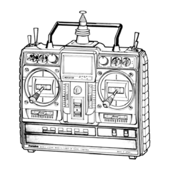
Thank you for purchasing a Futaba digital proportional radio control set. Please read this manual carefully before using your set The last page of this manual is a double foldout showing the name of each part of the transmitter. Please open it when reading this manual. -
Page 3: Table Of Contents
• TABLE OF CONTENTS SET CONTENTS ......... . . BEFORE USING . - Page 4 • SET CONTENTS *Specifications are subject to change without prior notice. FP-7UAP FP-7UAF Rating • FP-T7UAP ( X 1 ) • FP-T7UAF ( X 1 ) 2 s t i c k s , 7 channels, PCM or FM transmitter Transmitting frequency: 72MHz, 50MHz, •...
-
Page 5: Before Using
• BEFORE USING • Charging the transmitter and receiver Nicd battery *Use the special Futaba charger. FP-7UAPor FP-7UAF • The charging time is 15 hours. [However when the battery was not used for some time, charge and Charger discharge it 2 — 3 times. Otherwise,... - Page 6 • BEFORE USING • RECEIVER AND SERVO CONNECTIONS CH7 (AUX) Option CH6 Flap servo (sold separately) Pay careful attention to the Landing gear polarity of the connector. servo Antenna wire Rudder servo PCM receiver FP-R129DP, FP-R137GPor Throttle Four servos FM receiver FP-R-128DF servo are supplied as standard.
- Page 7 • The crystal can be changed from the outside of drain the battery pack very quickly. Make the the receiver case. Always use the Futaba trans- travel of each control mechanism somewhat larger than the full stroke (including trim) of mitter/receiver matched crystal set to change the servo horn.
- Page 8 • DISPLAY FUNCTION Liquid crystal panel • Operated in three display modes EDIT KEY DATA INPUT CURSOR MODE SELECT • Used in display mode switching. • Used at data setting. • Used in setting function selection Display Display mode at_normal use (Mode which is displayed when the power switch is turned on.) (Display) •...
- Page 9 • DISPLAY FUNCTION Function data setting display mode P.19 (Display) COMB P.18 STRM P.18 FLTR Function name P.18 Function setting parameters (See the individual function FLPR setting items.) P.10 P.17 DIFF PMX1 P.11 (Set function recall) P.16 • The function is selected by I MODE SELECT | key.
- Page 10 • FUNCTION AND DATA SETTING P r e s s t h e [MODE SELECT] To normal display mod* Function Display Data setting CH selection ADJUSTABLE TRAVEL Select the CH to which ATV is VOLUME to be applied with the keys.
-
Page 11: Exponential
• FUNCTION AND DATA SETTING To normal display mode Press the [MODE SELECT] Function Display Data setting CH selection EXPONENTIAL Select the CH to which EXP is to be applied with the This function modifies the operat- keys. ing curve so that operation is easy when the movement of the servos becomes sluggish or sensitive near D/R switch direction selection... -
Page 12: Fail Safe
*The F/S set data is automatically sent every minute. *The PPM mode does not have an F/S function. (FP-7UAF) *When using the B.F/S function, set the throttle channel F/S func- tion. To PMX1... -
Page 13: Programmable Mixing 1
• FUNCTION AND DATA SETTING To normal display mode Press the [MODE SELECT] PMX1 Mixing activate/inhibit mode setting PROGRAMMABLE MIXING 1 Set the mode with the keys. This mixing is useful in correcting + : Activate bad tendencies of the aircraft and —: Inhibit in making operation more pleasant. -
Page 14: Programmable Mixing 2
• FUNCTION AND DATA SETTING To normal display mode Press the [MODE SELECT] PMX2 Mixing activate/inhibit mode setting PROGRAMMABLE MIXING 2 Set the mode with the keys. This mixing is useful in correcting + : Activate bad tendencies of the aircraft and -: Inhibit in making operation more pleasant. -
Page 15: Elevator -> Flap Mixing
• FUNCTION AND DATA SETTING To normal display mode Pressthe [MODE SELECT] Mixing activate/inhibit mode setting > ELEVATOR -> FLAP MIXING Set the mode with the keys. + : Activate This is used to apply mixing from elevator to flap. Mixing is usually Inhibit used so that the flaps are lowered when the elevator is raised. -
Page 16: Flap -> Elevator Mixing
• FUNCTION AND DATA SETTING Press the [MODE SELECT] To normal display mode Activate/inhibit mode setting FLAP -> ELEVATOR MIXING Set the mode with the keys. + : Activate Use this mixing when an air brake -: Inhibit is necessary when landing or diving, etc. -
Page 17: Snap-Roll
• FUNCTION AND DATA SETTING To normal display mode Press the [MODE SELECT] Activate/inhibit mode setting SNAP-ROLL Set the mode with the keys. + : Activate -: Inhibit Avalanche and other snap rolls can be performed by switch. Select the direction (INH: Inhibit state) Switch RIGHT... -
Page 18: Aileron Differential
• FUNCTION AND DATA SETTING To normal display mode Pressthe (MODE SELECT] keys simultaneously DIFF Activate/inhibit mode setting AILERON DIFFERENTIAL Set the mode with the keys. + : Activate A left and right differential can be -: Inhibit applied to the ailerons. This is ef- fective in roll axis correction. -
Page 19: Flaperon
• FUNCTION AND DATA SETTING Press the [MODE SELECT] To normal display mode FLPR Activate/inhibit mode setting FLAPERON Set the mode with the keys. + : Activate This is a mixing function which Inhibit gives the ailerons a flap function. The ailerons can be raised and lowered... -
Page 20: Flap Trim
• FUNCTION AND DATA SETTING To normal display mode Press the. [MODE SELECT] FLTR Trim/normal mode setting FLAP TRIM Set the mode with the keys. + : Trim mode FLAP TRIM (CH6) lever operation — : Normal mode <-> normal operation switching is possible. -
Page 21: Modulation
• FUNCTION AND DATA SETTING • OTHER FUNCTIONS Press the [MODE S E L E C T] To normal display mode Mode selection MODULATION Select mode with keys. The modulation can be switched PCM <-> PPM mode. *When the mode was switched, the transmit- * Select the PCM mode for the FP- ter power switch is turned off and transmit 7UAP and the PPM mode for the... -
Page 22: Using The Accessories
• OTHER FUNCTIONS • USING THE ACCESSORIES • Trainer function (Trainer cable optional) 1 Connection to transmitter 2 Operating at the instructor side Trainer switch Operation is possible by turning on the instructor transmitter power switch. At this time, turn off the trainer switch. Student transmitter 3 Operating at the student side Instructor transmitter... -
Page 23: Using The Accessories
• Digital Proportional Frequencies (FOR U.S.A.) • The frequency of Futaba digital proportional sets can be changed within their own band. There are 2 different bands for you to choose from (27 MHz and 75 MHz.) Please see chart listed below for specific frequency and its intended use. -
Page 24: Nomenclature (Double Foldout)
• NOMENCLATURE Antenna Liquid crystal panel Carrying bar Neck strap hook Aileron trim lever RF module Rudder trim lever Trainer jack Charging jack Elevator trim lever..(MODE II) (w/dustcap) (w/dust cap) Throttle trim lever..(MODE I) Power switch Battery cover Throttle trim lever.. -
Page 25: Servo Exploded View
• SERVO EXPLODED VIEW FP-S148 FP-S3001 Part Name Part No. Part Name Part No. Upper case S06100 Upper case S06015 Middle case S06005 Middle case Bottom case S06006 S06005 Bottom case Metal bearing inner S04137 S06006 Metal bearing outer Metal bearing inner S04137 S04136 Metal bearing outer... - Page 26 Printed in Japan/900330CC...
Need help?
Do you have a question about the FP-7UAF and is the answer not in the manual?
Questions and answers