
Related Manuals for Nokia DTX-3 Series


Summary of Contents for Nokia DTX-3 Series
- Page 1 Customer Care Services Technical Documentation SERVICE MANUAL [NMP Part No. 0275712] DTX-3 PBX Connectivity Ter- minal Issue 1 4/03 Copyright 2003 Nokia Mobile Phones. All Rights Reserved...
-
Page 2: Amendment Record Sheet
Customer Care Services Technical Documentation Amendment Record Sheet Amendment Inserted Date Comments 05/2003 Issue 1 Issue 1 4/03 Copyright 2003 Nokia Mobile Phones. All Rights Reserved... - Page 3 Customer Care Services Technical Documentation Service Manual Structure General Information Modules Parts List with Schematic and Layout Diagrams Variants Service Software Instructions Service Tools Disassembly / Troubleshooting Accessories Issue 1 4/03 Copyright 2003 Nokia Mobile Phones. All Rights Reserved...
- Page 4 While every endeavour has been made to ensure the accuracy of this document, some errors may exist. If any errors are found by the reader, NOKIA MOBILE PHONES Ltd should be notified in writing. Please state:...
-
Page 5: Warnings And Cautions
4. Use only approved components as specified in the parts list. 5. Ensure all components, modules screws and insulators are correctly re-fit- ted after servicing and alignment. Ensure all cables and wires are reposi- tioned correctly. Issue 1 4/03 Copyright 2003 Nokia Mobile Phones. All Rights Reserved... -
Page 6: General Information
Customer Care Solutions DTX-3 Series Transceivers General Information Nokia Mobile Phones Ltd. Issue 1 4/03... -
Page 7: Table Of Contents
DTX-3 General Information CCS Technical Documentation Table of Contents Page No Introduction to DTX-3 (Nokia 32) ....................... 3 Product Concept Generally ........................ 3 Concept ..............................3 Nokia 32 Sales package contents ....................5 Technical Specifications ........................6 Mechanical Characteristics ....................... 6 Environmental Conditions ....................... -
Page 8: Introduction To Dtx-3 (Nokia 32)
Nokia 32 internal antenna is used when there is no need for an external antenna. The main purpose of Nokia 32 is to use it as a GSM router beside a company PBX. Com- pany calls to GSM numbers are routed via Nokia 32 in order to gain cost savings in GSM- to-GSM calls and the fixed telephone line is bypassed. - Page 9 Network Network After the Nokia 32 has been connected to a PBX, the PBX may require reconfiguration to route mobile targeted calls via the Nokia 32. This reconfiguration requires special know- how about the PBX. In order to perform successful installation, further information must be asked from the PBX supplier.
-
Page 10: Nokia 32 Sales Package Contents
DTX-3 CCS Technical Documentation General Information Nokia 32 Sales package contents Table 1: Nokia 32 sales package contents Item Name Type code Material code User’s Guide Connectivity Terminal TME-3 0600344 TME-4 0600342 Application Module DTX-3 0630596 Power Supply ACW-5B 0630526... -
Page 11: Technical Specifications
Longer term contact with water will cause per- manent damage. TME-3/TME-4 and DTX-3 do not break mechanically after a free fall from 100cm (about 40 inches) height to a concrete floor. Nokia Mobile Phones Ltd. Page 6 Issue 1 4/03... - Page 12 Customer Care Solutions DTX-3 Series Transceivers Modules Nokia Mobile Phones Ltd. Issue 1 4/03...
- Page 13 Table of Contents Page No Glossary of Terms ......................3 Functional Description of DTX-3 ..................5 Circuit Description .......................5 Interfaces and Connectors ....................5 Nokia 32 LED Indicators ....................6 LED Indicator status: ....................7 Signal tones ........................8 Key Sequences ......................8 Nokia Mobile Phones Ltd. Page 2...
-
Page 14: Glossary Of Terms
1-wire half duplex serial bus Micro Controller Unit MCU-DSP Interface MCU+ASIC+DSP asic, common name for whole family MAD2PR1 Modified MAD2 asic, pin count 144 instead of 176 MAD2WD1 MCU+ASIC+DSP with HSCSD specific changes Nokia Mobile Phones Ltd. Issue 1 4/03 Page 3... - Page 15 Public Switched Telephone Network Radio Frequency Subscriber Identity Module SMART PCMCIA interface ASIC Sulo PCMCIA interface ASIC for RPM-3 User Interface VCXO Voltage Controlled Crystal Oscillator VCTCXO Voltage Controlled Temperature Compensated Crystal Oscillator. Nokia Mobile Phones Ltd. Page 4 Issue 1 4/03...
-
Page 16: Functional Description Of Dtx-3
600 Ω Telephone interface /PBX Extension interface: Signals Value Off-Hook AC impedance 600 Ω On-Hook AC impedance 150k Ω On-Hook DC resistance 10M Ω Loop DC current Min. 15 mA, max. 120mA Nokia Mobile Phones Ltd. Issue 1 4/03 Page 5... -
Page 17: Nokia 32 Led Indicators
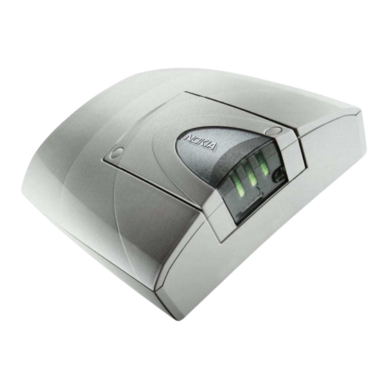
D9 female connector for standard level RS 232 data. Power Supply Connector Connector for ACW-5B power supply. Antenna connector TME-3 external antenna connector. Nokia 32 LED Indicators TME-3 comprises three indicator LEDs: Figure 1: Indicator LEDs Nokia Mobile Phones Ltd. Page 6... -
Page 18: Led Indicator Status
Green/Red blink Message received/ Voice mail in box Red blink Message storage full *) Led state due to current mode (trunk/extension) of the Nokia 32 terminal Table 3: Nokia 32 LED indicator status in special situations LED 1 LED 2... -
Page 19: Signal Tones
- - - - - - - - - - - - SMS received Key Sequences These sequences have to be entered using a normal landline telephone set connected to the trunk connector of Nokia 32 Nokia Mobile Phones Ltd. Page 8 Issue 1 4/03... - Page 20 DTX-3 CCS Technical Documentation Modules Table 4: Nokia 32 button sequences used in trunk mode. Sequence Functionality Response PIN# PIN code input Tone PUK# PUK code input Tone 0**value Volume control, louder. ‘Value’ from 1 to 10. Tone 555**# System reset...
- Page 21 DTX-3 Modules CCS Technical Documentation [ This page intentionally left blank. ] Nokia Mobile Phones Ltd. Page 10 Issue 1 4/03...
- Page 22 Customer Care Solutions DTX-3 Series Transceivers DTX-3 Parts List Nokia Corporation Issue 1 4/03...
- Page 23 DTX-3 Company confidential DTX-3 Parts List CCS Technical Documentation Table of Contents Variants of DTX-3 Nokia 32 ..................3 Transceiver Variants ....................3 Country-specific settings .....................3 DTX-3 Exploded Diagram .....................4 DTX-3 Assembly Parts List ..................5 Nokia Corporation. Page 2 Issue 1 4/03...
-
Page 24: Country-Specific Settings
Company confidential DTX-3 CCS Technical Documentation DTX-3 Parts List Variants of DTX-3 Nokia 32 Transceiver Variants Table 1: Name Type des. Code TME-3 Transceiver TME-3 0600344 TME-4 Transceiver TME-4 0600342 Country-specific settings The country code allows different country-specific settings to be activated in SWAP- module. - Page 25 The following picture shows the exploded view of DTX-3 module. The application module consists of two injection moulded plastic parts, frame and bracket for the Application Interface connector (pin header) and a PWB inside the mod- ule. Nokia Corporation. Page 4 Issue 1 4/03...
- Page 26 DTX-3 Parts List DTX-3 Assembly Parts List Table 2: Part Number in Part Name Material Code Exploded View l010 Filler plugs I011 Screws 3x18 T10 6150081 Nokia 30/Nokia31 TME-3 0600344 l012 A-cover 9458825 l013 JP-6 0201946 l014 B-cover 9458911 l015...
- Page 27 DTX-3 Company confidential DTX-3 Parts List CCS Technical Documentation [This page intentionally left blank.] Nokia Corporation. Page 6 Issue 1 4/03...
-
Page 28: Service Software
Customer Care Solutions DTX-3 Series Transceivers Service Software Nokia Corporation. Draft 2 3/03... - Page 29 Flash Concept for DTX-3 ....................8 Label printing .......................9 Identification ........................9 Product code......................9 SW version ......................10 PSN.......................... 10 Manufacture date..................... 10 HW version ......................10 Default factory values ....................10 Fault logger ........................11 Nokia Corporation. Page 2 Draft 2 3/03...
-
Page 30: General
PKD–1 ! Please refer to service setup in this chapter for information regarding different flash set- ups. Attach the dongle PKD–1 to the parallel port 1 (25–pin female D–connector) of the PC. Nokia Corporation. Draft 2 3/03 Page 3... -
Page 31: Installing The Service Software On Pc Hard Disk
First time installation of WinTesla: Do the following to make a complete WinTesla installation with support for DTX-3: Insert the WinTesla software diskette into the floppy drive on your computer (i.e. Drive Nokia Corporation. Page 4 Draft 2 3/03... -
Page 32: For Windows 3.1 And 3.11
When installation has finished remove the WinTesla software disk from your floppy drive. Insert the Dongle driver diskette into your floppy drive. Select the floppy drive and: Start installation, double–click the dk2wn32.exe file. Follow the instructions on the screen. Nokia Corporation. Draft 2 3/03 Page 5... -
Page 33: Installation Of Dtx-3 Support Modules (Wintesla Already Installed)
Service Software can also be downloaded from the following address: http://calns01net.europe.nokia.com/nmp/rd/pams/softrel.nsf/sr2 For Windows 98 and NT: Open Microsoft Explorer, select Start –Programs– Explorer Select the floppy drive. Start installation, double–click the asinstall.exe file. Follow the instructions on the screen. Nokia Corporation. Page 6 Draft 2 3/03... -
Page 34: Flash Instructions For Dtx-3
CCS Technical Documentation Service Software Flash Instructions for DTX-3 The Nokia 32 PBX Connectivity application module is flashed in the following way: 1 For flashing the DTX-3 application module, the Bus configuration must be changed to COMBOX. Select Configure -> Buses. -
Page 35: Flash Concept For Dtx-3
11 AXS-4 D9- D9 Cable 0730090 Printer Cable 0730029 13 PKD-1 Software Protection Key O750018 14 ACH-6E Charger 0675084 15 ACS-6E Charger 0680016 Service SW for DTX-3 can be downloaded from: http://www.nmp.nokia.com/nmp/ccsweb.nsf (software selection) Nokia Corporation. Page 8 Draft 2 3/03... -
Page 36: Label Printing
Choose Software -> Print Label Identification Choose Software -> Production Data The information should be readable, not editable. Product code The product code is shown same way as in N22 service application. Nokia Corporation. Draft 2 3/03 Page 9... -
Page 37: Sw Version
The HW version is shown same way as in N22 service application. Default factory values Figure 1: Choose Software -> Set Factory Values This command is used for re-setting factory values to the EEPROM of the Application Module. Nokia Corporation. Page 10 Draft 2 3/03... -
Page 38: Fault Logger
CCS Technical Documentation Service Software Fault logger The N32 PBX Connectivity application module fault logger works in TME-3/4 Phoenix. New module “reason” is PBX Application Module DTX-3, needs to be added to TME-3/4 Phoenix. Nokia Corporation. Draft 2 3/03 Page 11... - Page 39 DTX-3 Service Software CCS Technical Documentation [This page intentionally left blank.] Nokia Corporation. Page 12 Draft 2 3/03...
-
Page 40: Service Tools
Customer Care Solutions DTX-3 Series Transceivers Service Tools Nokia Corporation Issue 1 4/03... - Page 41 D9-D9 Cable AXS-4 ....................7 D15-D15 Cable AXS-5 ....................8 Service Cable DKT-6A ....................9 Line Adapter Test cable SCS-24 ................10 SW Security Device PKD-1 ..................11 Power Cable PCC-1B ....................12 Modular T-Adapter ....................13 MBUS Cable DKT-7A ....................14 Nokia Corporation Page 2 Issue 1 4/03...
-
Page 42: Flash Loading Adapter Fla-7
The adapter is connected to the flash prommer FPS-4 by the AXS-5 cable and to the security box TDF-4 by the XCM-1 cable. Product Code Flash Loading Adapter FLA-7: 0770119 Figure 1: View of FLA-7 Nokia Corporation Issue 1 4/03 Page 3... -
Page 43: Flash Prommer Fps-4 (Sales Pack)
RPM-3 specific files. Make sure that you have newest FPS-4 software before you start setting up SW upgrade equipment. Product Code Flash Prommer FPS-4: 00750090 Figure 2: View of FPS-4 Nokia Corporation Page 4 Issue 1 4/03... -
Page 44: Security Box Tdf-4
Note: TDF-4 is delivered in de-activated mode. Fill in the enclosed Activation Request Form, and fax to NMP Salo to get the activation code. Product Code Security Box TDF-4: 0770106 Figure 3: View of TDF-4 Nokia Corporation Issue 1 4/03 Page 5... -
Page 45: Dc Power Cable Scf-7
DC Power Cable SCF-7 The DC power cable SCF-7 is used for connecting power from ACL-3 charger via FLA-7 to FPS-4. Product Code DC Power Cable SCF-7: 0730141 Figure 4: View of SCF-7 Nokia Corporation Page 6 Issue 1 4/03... -
Page 46: D9-D9 Cable Axs-4
PC and TDF-4 security box. The D9-D9 cable AXS-4 is used to connect TDF-4 security box to FPS-4 Flash Prommer. Product Code D9 - D9 Cable AXS-4: 0730090 Figure 5: View of AXS-4 Nokia Corporation Issue 1 4/03 Page 7... -
Page 47: D15-D15 Cable Axs-5
CCS Technical Documentation D15-D15 Cable AXS-5 The D15-D15 cable AXS-5 is used to connect two 15-pin D-connectors, for example, between FLA-7 and FPS-4. Product Code D15-D15 Cable AXS-5: 0730091 Figure 6: View of AXS-5 Nokia Corporation Page 8 Issue 1 4/03... -
Page 48: Service Cable Dkt-6A
Service Cable DKT-6A is used to connect FLA-7 to DTX-3. One connector a 6-pin modular connector, the other is a 10-pin modular connector. Product Code Modular Cable DKT-6A: 0730213 Figure 7: View of DKT-6A Nokia Corporation Issue 1 4/03 Page 9... -
Page 49: Line Adapter Test Cable Scs-24
Line Adapter Test cable SCS-24 Line Adapter Test Cable SCS-24 is connected between trunk connector and T-adapter when testing the Nokia 32 Application Module. It consists of 50 cm flat 6-core cable with a 6-pin modular connector at each end... -
Page 50: Sw Security Device Pkd-1
Make sure that you have switched off the PC and the printer before mak- ing connections! Caution: Do not connect the PKD-1 to the serial port. You may damage your PKD- Product Code SW Security Device PKD-1: 0750018 Figure 9: View of PKD-1 Nokia Corporation Issue 1 4/03 Page 11... -
Page 51: Power Cable Pcc-1B
CCS Technical Documentation Power Cable PCC-1B Power Cable PCC-1B is used to connect the DTX-3 application module with the Flash Loading Adapter. Product Code Power Cable PCC-1B: 0770050 Figure 10: View of PCC-1B Nokia Corporation Page 12 Issue 1 4/03... -
Page 52: Modular T-Adapter
Service Tools Modular T-Adapter Modular T-Adapter is used in testing the Nokia 32 Application module. SCS-24 Line Adapter Test Cable from trunk Connector and CA-15DS Line Adapter test cable from extension connector are connected to the T-Adapter during loop test. DKT-7A MBUS Cable is also connected to the T-connector to make the connection to PC. - Page 53 DTX-3 Service Tools CCS Technical Documentation MBUS Cable DKT-7A Service MBUS cable connects the PC to the T-Adapter when testing the Nokia 32 Appli- cation Module. Product Code MBUS Cable DKT-7A: 0730211 Figure 11: MBUS Cable DKT-7A Nokia Corporation Page 14...
-
Page 54: Product Code
Service Tools Line Adapter Test Cable CA-15DS Line adapter test cable CA-15DS is connected between extension and T-connector (4626134) when testing the Nokia 32. It consists of 50cm of flat 6-core cable with 6-pin modular connector at each end. Product Code... - Page 55 DTX-3 Service Tools CCS Technical Documentation [This page intentionally left blank.] Nokia Corporation Page 16 Issue 1 4/03...
- Page 56 Customer Care Solutions DTX-3 Series Transceivers Disassembly and Troubleshooting Nokia Corporation Issue 1 4/03...
- Page 57 General .........................3 Equipment needed .......................4 Software needed ......................4 Visual overlook ......................4 Initial connections ......................5 Troubleshooting flowchart for Nokia 32 and DTM-3 ..........6 Troubleshooting flowchart for DTX-3 ................7 Testing with WinTesla service software ..............8 Nokia Corporation Page 2 Issue 1 4/03...
-
Page 58: Introduction
CCS Technical Documentation Disassembly and Troubleshooting Introduction The purpose of this document is to help in hardware troubleshooting of the Nokia 32 PBX Connectivity Terminal. TME-3/TME-4 troubleshooting is described in the TME-3/TME-4 manual. DTX-3 module is not designed to be repaired, except for the Application Interface Con- nector. -
Page 59: Troubleshooting
General The purpose of this document is to help the service point to solve which part of the radio is faulty. The service policy with the Nokia 32 connectivity terminal is, that only the TME- 3/TME-4 will be repaired. Both TME-3 and DTX-3 covers can be replaced if necessary. -
Page 60: Visual Overlook
6. Connect power cable between DTX-3 and ACW-5. 7. Connect mains cable between ACW-5 and mains plug. See the instructions on the bot- tom side of the adapter. 8. Choose Testing -> Self Tests... from Wintesla. Nokia Corporation Issue 1 4/03 Page 5... - Page 61 DTX-3 Disassembly and Troubleshooting CCS Technical Documentation DKT-7A SCS-24 ACW-5 DA-15DS Nokia 32 Nokia Corporation Page 6 Issue 1 4/03...
-
Page 62: Troubleshooting Flowchart For Nokia 32 And Dtm-3
DTX-3 CCS Technical Documentation Disassembly and Troubleshooting Troubleshooting flowchart for Nokia 32 and TME-3/TME-4 Start Factory reset DTX-3 self DTX-3 test pass ? failure Swap TME-3 Refer to TME-3 service instruction Disconnect T-piece from DTX-3 TRUNK connector and audio cable... -
Page 63: Troubleshooting Flowchart For Dtx-3
DTX-3 Disassembly and Troubleshooting CCS Technical Documentation Troubleshooting flowchart for DTX-3 DTX-3 failure Swap DTX-3 Set initial connections Set country parameter DTX-3 self test pass ? Nokia Corporation Page 8 Issue 1 4/03... -
Page 64: Testing With Wintesla Service Software
Figure 3: Test equipment set-up Type Description Code DTX-3 APPLICATION MODULE 0630596 ACW-5 POWER SUPPLY 0630526 DKT-7A MBUS CABLE 0730211 T-CONNECTOR 4626134 CA-15DS LINE ADAPTER TEST CABLE 0730302 SCS-24 LINE ADAPTER TEST CABLE 0730223 Nokia Corporation Issue 1 4/03 Page 9... - Page 65 Figure 4: Hook on/off test window 1 indicators Check that the Hook off/on indicator state will change when you change the hook state. If not, the DTX-3 is faulty. Figure 5: Hook on/off test window 2 indicators Nokia Corporation Page 10 Issue 1 4/03...
- Page 66 Send button and listen from the earpiece the DTMF tones. Check also from the 'Received string:' row, that all numbers that you just selected were transmitted. Figure 6: DTMF test window Received String field DTMF String field Nokia Corporation Issue 1 4/03 Page 11...
- Page 67 DTX-3 is probably broken. Activate the HF-state from the land-line telephone, or take the earpiece to listen the sig- nal tones. From the Tone generator field you can select different tones to be listened. Nokia Corporation Page 12 Issue 1 4/03...
-
Page 68: Self Tests
DTX-3 CCS Technical Documentation Disassembly and Troubleshooting Self tests The following build in selftests will be supported by Nokia 32 in addition to Nokia 22 selftests: • Line voltage • Ringing generation/detection • DTMF generation/detection • GSM link test For more detailed information see Ratti SW Selftest Functional Specification . - Page 69 CCS Technical Documentation Figure 8: Audio codec Test window If you can not hear these tones, the audio codec is probably faulty. Try to make also a test call with the land line telephone. Nokia Corporation Page 14 Issue 1 4/03...
- Page 70 Customer Care Solutions DTX-3 Series Transceivers Accessories Nokia Mobile Phones Ltd. Issue 1 4/03...
- Page 71 DTX-3 Accessories CCS Technical Documentation Table of Contents Page No RS-232 Data Cable ......................3 Product Code .......................3 Antenna Cable XRP-3 ....................4 Product Code .......................4 MBUS Cable DKT-7A ....................5 Product Code .......................5 Nokia Mobile Phones Ltd. Page 2 Issue 1 4/03...
-
Page 72: Rs-232 Data Cable
For sending and receiving of SMS, PC-Fax, file transfer, e-mail and internet access a standard RS-232 Data Cable is needed Product Code RS-232 Data Cable 0730029 Figure 1: RS-232 Data Cable Nokia Mobile Phones Ltd. Issue 1 4/03 Page 3... -
Page 73: Antenna Cable Xrp-3
CCS Technical Documentation Antenna Cable XRP-3 This adapter cable can be used to connect a standard FME antenna connector to TME-3. Product Code Antenna Cable XRP-3: 0730206 Figure 2: Antenna Cable XRP-3 Nokia Mobile Phones Ltd. Page 4 Issue 1 4/03... -
Page 74: Mbus Cable Dkt-7A
Service MBUS cable to connect PC to DTX-3 (trunk connector). It comprises a D9 con- nector and a modular 6-pin connector. Product Code MBUS Cable DKT-7A: 0730211 Figure 3: MBus cable DKT-7A Nokia Mobile Phones Ltd. Issue 1 4/03 Page 5... - Page 75 DTX-3 Accessories CCS Technical Documentation [This page intentionally left blank.] Nokia Mobile Phones Ltd. Page 6 Issue 1 4/03...
- Page 76 www.s-manuals.com...
Need help?
Do you have a question about the DTX-3 Series and is the answer not in the manual?
Questions and answers