HP E24i G4 Manual
- Maintenance and service manual (25 pages) ,
- Product end-of-life disassembly instructions (5 pages) ,
- Quick setup (2 pages)
Advertisement
Getting started
Read this chapter to learn about safety information and where to find additional HP resources.
Important service information and precautions
- Repair must be performed by professional service technicians in a repair center. End users should not perform these procedures.
- Please note during servicing that the primary side is the high voltage area.
- This monitor meets ROHS requirements. Be sure to use lead-free solder wire when soldering.
- If you must change a capacitor, be sure to match the polarity as printed on the PCB.
- If you must replace a capacitor, make sure the specification and part number match the BOM and location.
- If you must replace a capacitor, insert new parts carefully to avoid a short circuit caused by the near pin.
- Do not get the board wet. Water and moisture can cause a short circuit that causes malfunctions.
- To avoid damage, be sure to use lead-free solder.
- When soldering, work quickly to avoid overheating the circuit board.
- Keep the soldering iron tip clean and well tinned when replacing parts.
- After repair, perform a close inspection of the circuit board to confirm it is in good condition.
- After repair, perform a function test to confirm the power supply is working properly.
ERP Lot5 requirement
- A professional repairer must have the technical competence to repair electronic displays and comply with the applicable regulations for repairers of electrical equipment in the Member States where the repairer operates. Reference to an official registration system as professional repairer, where such a system exists in the Member States, shall be accepted as proof of compliance.
- A professional repairer must have insurance that covers liabilities resulting from repairs, regardless of whether required by the Member State.
General descriptions
This manual contains general information. There are two levels of service:
Level 1: Cosmetic/appearance/alignment service
Level 2: Circuit board or standard parts replacement
Firmware updates
Firmware updates for the monitor are available at support.hp.com. If no firmware is posted, the monitor does not need a firmware update.
Before returning the repaired product to the customer
Perform an AC leakage current check on exposed metallic parts to be sure the product is safe to operate without the potential of electrical shock. Do not use a line isolation transformer during this check.
Measurements that are not within specified limits present a possible shock hazard. You must check and repair the
product before returning it to the customer.
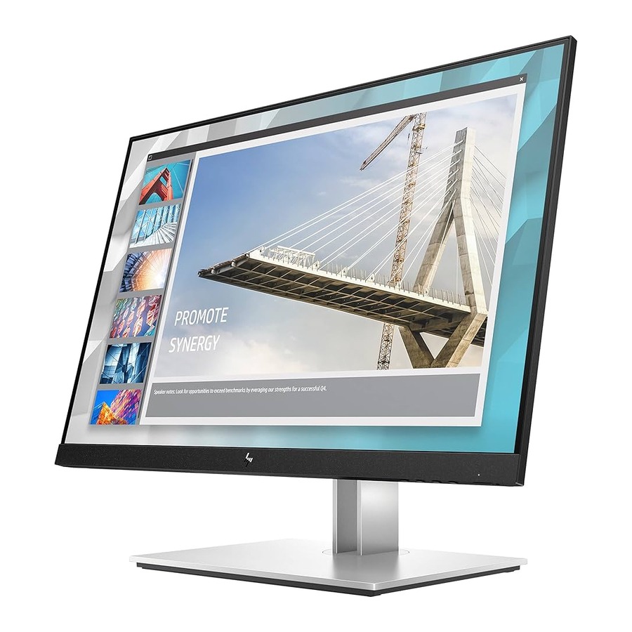
Monitor features
This chapter provides an overview of the monitor's features.
Features
Depending on the model, your monitor might include the following features:
61.0 cm (24.0 in) diagonal viewable screen area with 1920 × 1200 resolution
- In-plane switching (IPS) panel
- Non glare panel with an LED backlight
- Wide viewing angle to allow viewing from a sitting or standing position, or moving from side to side
- Tilt, swivel, and height adjustment capabilities
- Pivot capability to rotate the monitor head from landscape to portrait orientation
- Removable stand for flexible monitor head mounting solutions
- HP Quick Release 2 device to quickly attach the monitor head to the stand with a simple click, and then remove it with the convenient sliding tab release
- DisplayPort™ video input (cable included)
- High-Definition Multimedia Interface™ (HDMI) video input (cable included)
- VGA video input (cable included in select regions)
- USB hub with one USB Type-B port (cable included) that connects to the computer (upstream) and four USB ports that connect to USB devices (downstream)
- Four on-screen display (OSD) buttons, three that you can reconfigure to quickly allow selection of the most commonly used operations
- Plug and Play capability if supported by your operating system
- VESA® mounting bracket for attaching the monitor head to a wall-mount device or swing arm
- Security cable slot on the rear of the monitor for an optional security cable
- Cable management feature for placement of cables and cords
- On-screen adjustments in several languages for easy setup and screen optimization
- Energy saver feature to meet requirements for reduced power consumption
NOTE: For safety and regulatory information, refer to the Product Notices provided in your documentation kit. To access the latest user guides or manuals for your product, go to http://www.hp.com/support and follow the instructions to find your product. Then select Manuals.
Front components
To identify the components on the front of the monitor, use this illustration and table.
Press the power button on the bottom of the monitor to turn it on.

Rear components
To identify the components on the rear of the monitor, use this illustration and table.

Table 1-1: Rear components and their descriptions
| Component | Function | |
| 1 | Security cable slot | Connects an optional security cable. |
| 2 | Power connector | Connects the power cord |
| 3 | VESA release button | Connects the DisplayPort cable to a source device such as a computer or game console |
| 4 | DisplayPort connector | Connects the DisplayPort cable to a source device such as a computer or game console |
| 5. | HDMI port | Connects the HDMI cable to a source device such as a computer or game console |
| 6 | VGA port | Connects the VGA cable to the source device |
| 7 | USB Type-B port (upstream) | Connects the USB Type-B cable to a source device such as a computer or game console. |
| 8 | USB ports (2) (downstream) | Connect a USB cable to a peripheral device, such as a keyboard, mouse, or USB hard driver |
| 9 | USB ports (2) (downstream) | Connect a USB cable to a peripheral device, such as a keyboard, mouse, or USB hard drive. |
Locating the serial number and product number
Depending on the product, the serial number and product number are located on a label on the rear of the monitor or on a label under the front bezel of the monitor head. You might need these numbers when contacting HP about the monitor.

For worldwide models (except India):
Barcode label and spec label


For India: (N/A)
Illustrated parts catalog
To identify the monitor major components, use this illustration and table.

| item | part name | q'ty |
| 1 | HP LOGO | 1 |
| 2 | DECO | 1 |
| 3 | LENS POWER | 1 |
| 4 | PANEL | 1 |
| 5 | MYLAR | 1 |
| 6 | POWER BOARD | 1 |
| 7 | SCALAR BOARD | 1 |
| 8 | MYLAR | 1 |
| 9 | MAINFRAME | 1 |
| 10 | MIDDLE FRAME | 1 |
| 11 | USB BOARD | 1 |
| 12 | USB SHIELD | 1 |
| 13 | SPRING | 2 |
| 14 | RELEASE BUTTON | 1 |
| 15 | KEY BOARD | 1 |
| 16 | KEY BUTTON | 1 |
| 17 | REAR COVER | 1 |
| 18 | HP LOGO | 1 |
| 19 | RUBBER FOOT | 1 |
| 20 | STAND | 1 |
| S1 | SCREW M3 X6 | 5 |
| S2 | SCREW M4 X6 | 1 |
| S3 | SCREW M3 X4 | 11 |
| S4 | SCREW Q3 X4 | 3 |
| S5 | SCREW M4 X4 | 4 |
How to order parts
The HP authorized repair center can purchase the adaptor from HP.
Power board
| Description | HP spare part number | Manufacturer part number |
| E24i G4 | M97946-001 | PLPCJE441AQA1 |
| E24i G4 | M97947-001 | PLPCJE481KQA5 |
| E24i G4 | M97948-001 | PLPCJE461GQA6 |
Capacitors and connectors are available for purchase from the following EU distributors:
- Farnell: Farnell UK - Electronic Components Distributor
- RS Component: Capacitors | RS Components (rs-online.com)
- DK: https://www.digikey.com/
Capacitors by distributor
| Component description | Location | Component distributor | Distributor part number |
| 470uF 20% 25V 10*12.5 5000hr 1450mA | C904 | RS | EEUFR1E471 |
| 470uF 20% 25V 10*12 10000hr 1.7A P5.0 | C916 | RS | NRZJ471M25V10X12.5F |
Connectors by manufacturer
| Component description | Location identifier | Component distributor | Distributer part number |
| USB 3.0 TYPE A R/A 18P H16.42MM | CN103 | DK | WM10420-ND (0484060003) |
| USB 3.0 TYPE B | CN7732 | DK | 732-3158-ND (692221030100) |
| D-SUB | CN503 | DK | WM12594-ND (1731090066 1731090066) |
| HDMI | CN502 | DK | SAM14939TR-ND SAM14939CT-ND SAM14939DKR-ND (HDMR-19-02-S-SM-TR) |
| DP | CN501 | DK | WM19271TR-ND WM19271CT-ND WM19271DKR-ND (0472720001) |
NOTE: Rear cover and chassis need to be modified to hold connector. Connector may need modifications to meet functional, safety and regulatory requirements accordingly if it doesn't match exactly.
You can purchase cables from the HP part store at https://partsurfer.hp.com/Search.aspx.
NOTE: HP continually improves and changes product parts. For complete and current information about supported parts for your computer, go to http://partsurfer.com, select your country or region, and then follow the on-screen instructions.
Internal and External Power Supplies are available for purchase from the following EU distributor: EET https://www.eetgroup.com/en-eu/
Removal and replacement procedures
Adherence to these procedures and precautions is essential for proper service.
Preparation for disassembly
Use this information to properly prepare to disassemble and reassemble the monitor.
Read the "Important safety information" and "Important service information and precautions" sections in the "Getting started" chapter of this guide.
Clean the room for disassembly.
Identify the disassembly area.
Check the position that the monitors are to be placed along with the number of monitors. Prepare the area for material flow according to the disassembly layout.
Be sure to have the following equipment and materials:

- Press fixture
- Working table
- Screwdriver
- Knife
- Gloves
- Cleaning cloth
- ESD protection
- Scraper bar in the following dimensions:
Rear cover
Before removing the rear cover follow these steps:
- Prepare the monitor for disassembly. See Preparation for disassembly.
Remove the Rear cover:
| Step | Figure | Description |
| Remove the HINGE ASS'Y |  | Remove the hinge assy by press the hook on the rear cover. |
| Remove the rear cover |  | Remove the rear cover screws by the screwdriver. |
 | Remove the rear cover from the top side | |
 | disconnect the connectors | |
 | ||
 | Disconnect the connecters | |
| Remove the mylar |  | Tear out all tapes and disconnect the connectors by hand |
| Remove the power board |  | Remove the screws by the screwdriver |
| Remove the main board |  | Remove the screws by the screwdriver |
 | Remove the hex screws by the hex screwdriver | |
| Remove the USB board |  | Remove the screws by the screwdriver |
| Remove the middle frame |  | Remove the screws by the screwdriver |
| PANEL |  |
Power board
The power board part number is PLPCJE461GQA6.
Before removing the power board, follow these steps:
- Prepare the monitor for disassembly. See Preparation for disassembly.
Remove the power board:
- The HP E24i G4 power board connector position is as follows:
![]()

Locate the part number location on the board.

Connector repair
This procedure includes HDMI, Display Port, USB and VGA connectors.
The connectors are on the main board (board part numberCBPCNA6H0FD).
The connectors identifiers are as follows:
| Connector | Location |
| Display Port | CN501 |
| HDMI | CN502 |
| VGA | CN503 |
| USB 3.0 TYPE B | CN7732 |
| USB 3.0 TYPE A | CN103 |

Before repairing connectors, follow these steps:
- Prepare the monitor for disassembly. See Preparation for disassembly .

- Repair Condition: Connector repair is only for out of warranty.
- Repairing must operate by professional repairers (Note) in repair center, not applicable for end user.
- Electrostatic protection is required when component replacement is required.
- The monitor meets ROHS, please use Lead-free solder wire for soldering.
- If Connector need to replace, must check specification and part number whether match the BOM and location.
- If connector need to replace, please insert new parts carefully because the near pin may cause short circuit by inappropriate operate.
- DO NOT allow any liquid on the board. Water and moisture may cause short-circuit to the electronic components and lead to malfunctions.
- The fusion point of Lead-Free solder is requested. Repairing with conventional lead wire may cause damage.
- Work quickly to avoid overheating the circuit board as soon as you confirm the steady soldering condition.
- Keep the soldering iron tip clean and well tinned and when replacing parts.
- A close inspection of the circuit board revealed look in good condition.
- After repaired, must connect source to each port to check Main board function is ordinary.
Note: (The requirement of professional repairers' regulation by ERP lot5)
- The professional repairer has the technical competence to repair electronic displays and complies with the applicable regulations for repairers of electrical equipment in the Member States where it operates. Reference to an official registration system as professional repairer, where such system exists in the Member States concerned, shall be accepted as proof of compliance with this point.
- The professional repairer is covered by insurance covering liabilities resulting from its activity, regardless of whether this is required by the Member State.
USB 3.0 TYPE B CN7732
Repair the usb connector:
- Use a hot air gun to melt the solder on the pins. Pin solder with soldering iron and absorber. You can gently push down with the soldering iron once everything is molten to move the CN7732 out of the through holes.

- Lift the CN7732 connector from the PCB.
- Place the new component on the PCB. Be sure that it matches the PCB footprint.
- Solder the new component.

USB 3.0 TYPE A CN103
Repair the audio connector:
- Use a hot air gun to melt the solder on the pins. Pin solder with soldering iron and absorber. You can gently push down with the soldering iron once everything is molten to move the CN103 out of the through holes.

- Lift the CN103 connector from the PCB.
- Place the new component on the PCB. Be sure that it matches the PCB footprint.
- Solder the new component.

VGA CN503
Repair the VGA connector:
- Use a hot air gun to melt the solder on the pins. Pin solder with soldering iron and absorber. You can gently push down with the soldering iron once everything is molten to move the CN503 out of the through holes.

- Lift the CN503 connector from the PCB.

- Place the new component on the PCB. Be sure that it matches the PCB footprint.
- Solder the new component.
HDMI connector CN502
Repair the HDMI connector:
- Use a soldering iron and a desoldering pump to remove as much solder as possible from the pin.
![]()
- Use a hot air gun to melt the solder on the pins.
![]()
- Lift the CN502 connector from the PCB.
- Place the new component on the PCB. Be sure that it matches the PCB footprint.
Solder the new component.


DP connector CN501
Repair the DP connector:
- Use a soldering iron and a desoldering pump to remove as much solder as possible from the pin.

- Use a hot air gun to melt the solder on the pins.

- Lift the CN501 connector from the PCB.
- Place the new component on the PCB. Be sure that it matches the PCB footprint.
- Solder the new component.


Function test
Table 4-1: Function test
| Test item | Operating description | Tool used |
| HDMI test | Confirm whether image displays and sound plays correctly on the monitor | Computer or DVD player |
| DP test | Confirm whether image displays and sound plays correctly on the monitor | Computer or DVD player |
| Audio test | Change volume and balance to confirm whether volume is smooth and loud enough | Speaker |
Support and troubleshooting
The following table lists possible problems, the possible cause or each problem, and the recommended solutions.
Table 4-2: Solving common problems
| Problem | Possible cause | Solution |
Screen is blank or video is flashing | Power cord is disconnected. | Connect the power cord. |
| Monitor is off. | Power the power button. NOTE: If pressing the Power button has no effect, press and hold the power button for 10 seconds to disable the Power button lockout feature. | |
| Video cable is improperly connected. | Connect the video cable properly. | |
| System is in Sleep mode. | Press any key on the keyboard or move the mouse to exit | |
| Sleep mode. | ||
| Video card is incompatible. | Open the OSD menu and select the Input Control menu. Set Auto-Switch Input to Off and manually select the input | |
Image appears blurred, indistinct, or too dark | Brightness is too low. | Open the OSD menu and select Brightness to adjust the brightness scale as needed. |
Check Video Cable is displayed on screen | Monitor video cable is disconnected. | Connect the appropriate video signal cable between the computer and monitor. Be sure that the computer power is off while you connect the video cable. |
Input Signal Out of Range is displayed on screen | Video resolution and/or refresh rate are set higher than what the monitor supports. | Change the settings to a supported setting. |
| The monitor is off, but it did not seem to enter into Sleep mode | The monitor's power saving control is disabled. | Open the OSD menu and select Power Control > AutoSleep Mode and set auto-sleep to On. |
On-Screen Menus are Locked is displayed | The monitor's OSD lock function is enabled. | Press and hold the Menu button on the front bezel to 10 seconds to disable the OSD lockout function. |
Power Button is Locked is Displayed | The monitor's power button is locked. | Press and hold the power button for 10 seconds to disable the power button lock function. |
Important safety information
Carefully read the cautions and notes within this document to minimize the risk of personal injury to service personnel. The cautions and notes are not exhaustive. Proper service methods are important to the safe, reliable operation of equipment. Improper service methods can damage equipment.
The service procedures recommended and described in this service manual provide effective methods of performing service operations. Service engineers should have prior repair knowledge and experience as well as appropriate training for the product before performing service procedures.
- Be sure your working environment is dry and clean and meets all government safety requirements.
- Be sure that other persons are safe while you are servicing the product.
- Do not perform any action that can cause a hazard to the customer or make the product unsafe.
- Use proper safety devices to ensure your personal safety.
- Always use approved tools and test equipment for servicing.
- Never assume the product's power is disconnected from the main power supply. Check that it is disconnected before opening the product's cabinet.
- Modules containing electrical components are sensitive to electrostatic discharge (ESD). Follow ESD safety procedures while handling these parts.
- Some products contain more than one battery. Do not disassemble or expose a battery to high temperatures, such as throwing into fire, or the battery may explode.
- Refer to government requirements for battery recycling or disposal.
This information provides general service information for the monitor. Adherence to the procedures and precautions is essential for proper service.
Only trained service personnel who are familiar with this HP product should perform service or maintenance for it. Before performing any service or maintenance, personnel must read the important safety information.
You must disconnect the power cord from the power source before opening the monitor to prevent component damage.
Documents / Resources
References
http://support.hp.com
http://www.hp.com/support
![uk.rs-online.com]() https://uk.rs-online.com/web/c/passive-components/capacitors/
https://uk.rs-online.com/web/c/passive-components/capacitors/HP PartSurfer
![partsurfer.com]() http://partsurfer.com
http://partsurfer.com![www.eetgroup.com]() EET International
EET International

Download manual
Here you can download full pdf version of manual, it may contain additional safety instructions, warranty information, FCC rules, etc.
Advertisement


Need help?
Do you have a question about the E24i G4 and is the answer not in the manual?
Questions and answers