HP 734pm, 7 Pro Series Manual
- Maintenance and service manual (25 pages) ,
- Maintenance and service manual (28 pages) ,
- Maintenance and service manual (26 pages)
Advertisement
Getting started
Read this chapter to learn about safety information and where to find additional HP resources.
General descriptions
This manual contains general information. There are two levels of service:
Level 1: Cosmetic/appearance/alignment service
Level 2: Circuit board or standard parts replacement
Firmware updates
Firmware updates for the monitor are available at support.hp.com. If no firmware is posted, the monitor does not need a firmware update.
Before returning the repaired product to the customer
Perform an AC leakage current check on exposed metallic parts to be sure the product is safe to operate without the potential of electrical shock. Do not use a line isolation transformer during this check.
Measurements that are not within specified limits present a possible shock hazard. You must check and repair the product before returning it to the customer.
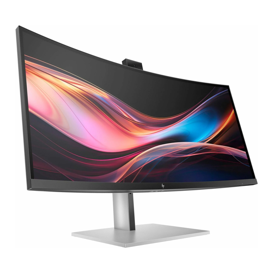
Monitor features
This chapter provides an overview of the monitor's features.
Features
Depending on the model, your monitor might include the following features:
Display features
- 86.4 cm (34 in) diagonal viewable screen area with 3440 × 1440 resolution (WQHD) or 95.3 cm (37.5 in) diagonal viewable screen area with 3840 × 1600 resolution (WQHD+), plus full-screen support for lower resolutions; includes custom scaling for maximum image size while preserving original aspect ratio
- Liquid crystal display (LCD) with active matrix and in-plane switching (IPS) Black Technology
- Wide color gamut to provide coverage of sRGB, Display P3, and BT.709 color spaces
- Nonglare panel with an LED backlight
- Wide viewing angle to allow viewing from a sitting or standing position, or moving from side to side
- Tilt, swivel, and height adjustment capabilities
- Internal speakers up to 76 dB @ 200 Hz bass roll-off (WQHD) or 85 dB @ 160 Hz bass roll-off (WQHD+)
- Dual Picture-in-Picture (PiP) and Picture-by-Picture (PbP) functionality to enable the USB Type C® Thunderbolt™, DisplayPort™, or HDMI inputs to be viewed where one image is overlaid onto another (PiP) or where one image is positioned adjacent to another (PbP)
- Five on-screen display (OSD) buttons, four that you can reconfigure to quickly allow selection of the most commonly used operations
- On-screen display (OSD) adjustments in several languages for easy setup and screen optimization
- Color space presets for Display P3
- Pantone Validated
- Compatible with displays software including Device Bridge 2.0
- Plug and Play capability, if supported by your operating system
- Energy saver feature to meet requirements for reduced power consumption
- Security cable slot on the rear of the monitor for an optional security cable
- Cable management feature for placement of cables and cords
Connectors
- DisplayPort video input/output (cable included for select products only)
- High-Definition Multimedia Interface (HDMI) video input (cable included for select products only)
- USB Type-C Thunderbolt port (cable included)
- USB Type-C Thunderbolt DisplayPort output
- USB hub with one USB Type-C port that connects to the computer (upstream) and six USB ports that connect to USB devices (downstream) (USB Type-C–to–USB Type-A cable included for select products only)
- RJ-45 (network) jack
Monitor stand
- Removable stand for flexible monitor head mounting solutions
- HP Quick Release 2 device to quickly attach the monitor head to the stand with a simple click, and then remove it with the convenient sliding tab release
- VESA® mounting bracket for attaching the monitor head to a wall-mount device or swing arm
- Support for a mounting bracket to attach the monitor to a workstation
NOTE: For safety and regulatory information, refer to the Product Notices provided in your documentation kit. To access the latest user guides or manuals for your product, go to http://www.hp.com/support and follow the instructions to find your product. Then select Setup & User Guides.
Front components
To identify the components on the front of the monitor, use this illustration and table.

Table 2-1 Front components and their descriptions
| Component | Description | |
| (1) | Ambient light sensor | Adjusts the display brightness according to lighting conditions in the environment. |
| (2) | Power button | Turns the monitor on or off. NOTE: When applicable HP products are connected to the USB Type-C Thunderbolt port, pressing the power button on the display turns on/off your notebook, or puts it to sleep based on your power setting (Performance mode). |
| (3) | Power LED | Indicates that the monitor is powered on or off. |
Camera components
(camera model only)
To identify the components on the camera, use this illustration and table.

Table 2-2 Camera components (camera model only)
| Component | Description | |
| (1) | Microphone | Features active noise cancellation. |
| (2) | Webcam LED | Indicates that the webcam is powered on. |
| (3) | Ambient light sensor (top) | Adjusts the display brightness according to lighting conditions in the environment. |
| (4) | RGB camera | Allows you to perform RGB video recording. |
| (5) | Infrared webcam | Allows you to use Windows Hello for facial recognition and provides better operation in low-light situations. |
| (6) | Infrared LED | Indicates the status of the infrared webcam. |
| (7) | Microphone | Features active noise cancellation. |
| (8) | User proximity sensor | Uses the Auto Lock and Awake feature to monitor your presence in front of the computer to save power and add security. When you step away from the computer, the proximity sensor puts the computer into the Sleep state. When you return to the computer, your computer recognizes you and wakes the computer automatically. Auto Lock and Awake is turned on by default. If you also want to set up facial recognition login for Auto Lock and Aware. |
Rear and side components
To identify the components on the rear of the monitor, use this illustration and table.

Table 2-3 Rear components and their descriptions
| Component | Description | |
| (1) | Joypad | Press to open the OSD settings. |
| (2) | Security cable slot | Connects an optional security cable. |
| (3) | Power connector | Connects your monitor to a power outlet. |
| (4) | USB Type-A port (includes KVM connection) | Connects a USB cable to a peripheral device, such as a keyboard, mouse, or USB hard drive, and charges peripheral devices. This is the dedicated USB Type-A port for KVM functions. It supports the KVM hot-key function on a keyboard that is connected to this port. |
| (5) | USB Type-C port (BC 1.2) | Connects a USB Type-C cable to a peripheral device, such as a keyboard, mouse, or USB hard drive and charges up to 5 V/3 A. |
| (6) | HDMI port | Connects the HDMI cable to a source device such as a computer. |
| (7) | DisplayPort | Connects the DisplayPort cable to a source device such as a computer. |
| (8) | DisplayPort OUT connector | Connects the monitor to another monitor for multistreaming. NOTE: If you need to remove the DisplayPort cable from the DisplayPort OUT connector, you should first remove the following cables in the order shown:
|
| (9) | USB Type-C DisplayPort port 2 (upstream) | Connects a Thunderbolt or USB Type-C DisplayPort cable to a source device such as a computer or game console. This USB Type-C port can function as a DisplayPort input or as a USB 3.0 connection. It can also be used to deliver up to 65 W of power to a device. Power outputs are 20 V/3.25 A, 15 V/4.33 A, 12 V/5 A, 9 V/3 A, or 5 V/3 A to achieve a 65 W output. This port also enables the USB Type-A ports to perform their functions. |
| (10) | USB Type-C Thunderbolt output port | Connects the monitor to another monitor for multistreaming. |
| (11) | USB Type-C Thunderbolt port 1 (upstream) | Connects a Thunderbolt or USB Type-C DisplayPort cable to a source device such as a computer or game console. This Thunderbolt port can function as a DisplayPort input or as a USB 3.0 connection. It can also be used to deliver up to 100 W of power to a device. Power outputs are 20 V/3.25 A, 15 V/4.33 A, 12 V/5 A, 9 V/3 A, or 5 V/3 A to achieve a minimum 65 W output. This port also enables the USB Type-A ports to perform their functions. |
| (12) | RJ-45 (network) jack | Network (RJ-45) data rate via USB Type-C max speed is 1000 Mbps
NOTE: This network port is fully energy efficient according to IEEE standards (IEEE 802.3az-2010) as long as all connected devices support this feature. |
| (13) | USB Type-A ports (3) | Connect a USB cable to a peripheral device, such as a keyboard, mouse, or USB hard drive. NOTE: This port also serves as the dedicated port for the Text-to-Speech (TTS) adapter (the first USB Type-A port from left to right). |
| (13) | USB Type-A ports (downstream) | Connects a USB cable to a peripheral device, such as a keyboard, mouse, or USB hard drive. |
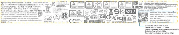
Locating the serial number and product number
The serial number and product number are located on the rear of the monitor. You may need these numbers when contacting HP about the monitor model.

For all regions:
Barcode label & Spec label
Illustrated parts catalog
To identify the monitor major components, use this illustration and table.

Table 3-1: Monitor major components and their descriptions
| Item | Description | Part number | Qty |
| 1 | #panel module | 1 | |
| 2 | #front bezel logo | 1 | |
| 3 | #front bezel metal | 1 | |
| 4 | # front bezel poron | 1 | |
| 5 | # front bezel adhesive | 3 | |
| 6 | # front bezel lens | 1 | |
| 7 | # front bezel plastic | 1 | |
| 8 | #middle frame | 1 | |
| 9 | #power key | 1 | |
| 10 | #webcam PMMA | 2 | |
| 11 | #ALS BD | 1 | |
| 12 | #webcam front cover | 1 | |
| 13 | #webcam module | 1 | |
| 14 | #webcam holder | 1 | |
| 15 | #webcam back cover | 1 | |
| 16 | #speaker | 1 | |
| 17 | #power BD | 1 | |
| 18 | #bottom USB BD | 1 | |
| 19 | #driver BD | 1 | |
| 20 | #audio BD | 1 | |
| 21 | #interface BD | 1 | |
| 22 | #sunk USB BD | 1 | |
| 23 | #hi-pot mylar | 1 | |
| 24 | #main bracket | 1 | |
| 25 | #hinge bracket | 1 | |
| 26 | #stand hinge | 1 | |
| 27 | #OSD BD | 1 | |
| 28 | #OSD key | 1 | |
| 29 | #rear cover | 1 | |
| 30 | #rear cover logo | 1 | |
| 31 | #stand column | 1 | |
| 32 | #stand base | 1 | |
| 21 | #interface BD | 1 | |
| 22 | #sunk USB BD | 1 |
How to order parts
The HP authorized repair center can purchase the power board from HP.
Power board
| Description | HP spare part number | Manufacturer part number |
| POWER BD MC34UHC-CJCL(C)734pm | N97156-001 | 755.0AX11.D005 |
Capacitors and connectors are available for purchase from the following EU distributors:
- Digi-Key(RUBYCON ALU CAP): www.digikey.com
Capacitors by distributor
| Component description | Location | Component distributor | Distributor part number |
| CAP EL 1000U 35V M P5 12.5*20 HX | AC651,AC652,AC654,AC655 | SUSCON | HX035M102X20T014P50R |
| CAP EL 1000U 35V M P5 13*20 ZH | CAPXON | ZH102M035I200ETABR |
Connectors by manufacturer
| Component description | Location identifier | Component distributor | Distributer part number |
| HDMI | HDMI1 | CUI Devices | https://www.digikey.com PN: HD12-19-SMT-TR |
| DP | DP1 DP2 | Molex | https://www.digikey.com PN: 2041441-1 |
| USB-C | USBC1(Main BD) USBC1(TBT BD) USBC2(TBT BD) | Molex | https://www.digikey.com PN: 2385692-1 |
| USB-C | USBC3(Bottom BD) | TE Connectivity | https://www.digikey.com PN: 2385692-1 |
| RJ45 | RJ45 | Amphenol ICC | https://www.digikey.com PN: RJLSE4238101TTR |
| USB-A | USB1(Main BD) USB2(Main BD) USB3(Main BD) USB4(Main BD) | Molex | https://www.digikey.com PN: 0484080003 |
| USB-A | USB5(Bottom BD) | Molex | https://www.digikey.com PN: WM10413TR-ND |
NOTE: The connector may need to be modified to meet functionality, regulatory and safety requirements if it is not an exact match.
You can purchase cables from the HP part store at https://partsurfer.hp.com/Search.aspx.
NOTE: HP continually improves and changes product parts. For complete and current information about supported parts for your computer, go to http://partsurfer.com, select your country or region, and then follow the on-screen instructions.
Internal and External Power Supplies are available for purchase from the following EU distributor: EET https://www.eetgroup.com/en-eu/
Removal and replacement procedures
Adherence to these procedures and precautions is essential for proper service.
Preparation for disassembly
Use this information to properly prepare to disassemble and reassemble the monitor.
- Read the "Important safety information" and "Important service information and precautions" sections in the "Getting started" chapter of this guide.
- Clean the room for disassembly.
- Identify the disassembly area.
- Check the position that the monitors are to be placed along with the number of monitors. Prepare the area for material flow according to the disassembly layout.
- Be sure to have the following equipment and materials:
- Press fixture
- Working table
- Screwdriver
- Knife
- Gloves
- Cleaning cloth
- ESD protection
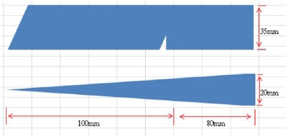
- Scraper bar in the following dimensions:
![]()
Rear Cover
Before removing the Rear Cover, follow these steps:
- Prepare the monitor for disassembly. See Preparation for disassembly.
- Remove webcam tape and caps from Display Head

- Remove Stand Base From Display Head by pushing the release button

- Remove Rear Cover From Display Head: Loose all the hooks by hand in order for pulling the rear cover, and disconnect the key cable away from the connector.

- Remove OSD key board from the rear cover: remove 1pcs screw

- Remove 2pcs tape, two speakers and hinge from Display Head. (6+4 pcs screws)

- Remove 3pcs acetate tape and 3pcs AL foil, then disconnect all the cables from the main chassis. And remove 1pcs screws for releasing bottom USB board

- Remove 4pcs screws and disconnect EDP cable from panel, then lift up and remove the main bracket chassis away from panel.

- Remove webcam Assy From Display Head by unlocking 4pcs screws and tearing off tape

- Remove Middle Frame from the Display Head: remove 26pcs(24+2) screws

- Remove Power key Board from Middle Frame

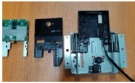
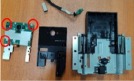
- Remove all the circuit board and AC connect from bracket Assembly by unlocking 14pcs screws


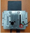
- Disassembly webcam Assy
- Release 1PCS screw and then remove webcam key PCB
![]()
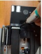
- Release webcam cable switch
![]()
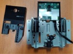
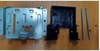
- Remove cable and 2PCS screw then remove front cover
![]()
- Remove webcam module and AL holder
![]()
- Remove gasket and ALS BD
![]()
- Release 3PCS screw from webcam module and AL holder
![]()
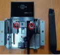
- Release 4PCS screw and then remove Spring and guide rod
![]()
![]()
- Release 1PCS screw and then remove webcam key PCB


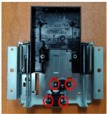
Power board
The power board part number is 755.0AX11.D005.
Before removing the power board, follow these steps:
- Prepare the monitor for disassembly. See Preparation for disassembly.
Remove the power board:
- The HP Series 7 Pro 734pm power board connector position is as follows:

- Locate the part number location on the board.

- Pin solder with soldering iron and absorber.
NA - Lift the connector up and away from the PCB.
NA


Connector repair
This procedure includes HDMI, Display Port, USB-C, TBT4, RJ45, USB-A connectors.
The connectors are on the main board (board part number 7ZB.0AX01.0008).
This procedure includes TBT4 connectors.
The connectors are on the TBT4 Board (board part number 755.0AX02.T001).
This procedure includes USB-A connectors.
The connectors are on the Sunk Board (board part number 755.0AX04.T001).
This procedure includes USB-A, USB-C connectors.
The connectors are on the Bottom Board (board part number 755.0AX03.T001)
The connector identifiers are as follows:
| Connector | Location |
| HDMI | HDMI1 (main BD) |
| DP | DP1, DP2 (main BD) |
| USB-C | USBC1 (main board), USBC3 (Bottom BD) |
| TBT4 | USBC1, USBC2 (TBT4 BD) |
| RJ45 | RJ451 (main board) |
| USBA | USB1, USB2 (main BD), USB3, USB4 (Sunk BD) |
| USBA | USB5 (Bottom BD) |

Before repairing connectors, follow these steps:
- Prepare the monitor for disassembly. See Preparation for disassembly.
HDMI connector HDMI1
Repair the HDMI connector:

- Use a hot air gun to melt the solder on the pins from the bottom side.
- Lift the HDMI connector from the PCB.
- Place the new component on the PCB. Be sure that it matches the PCB footprint.
- Solder the new component.
DP connector DP1/DP2
Repair the DP connector:

- Use a hot air gun to melt the solder on the pins from the bottom side.
- Lift the DP connector from the PCB.
- Place the new component on the PCB. Be sure that it matches the PCB footprint.
- Solder the new component.
USB-C connector USBC1/USBC2
Repair the USB-C connector:

- Use a hot air gun to melt the solder on the pins from the bottom side.
- Lift the USB-C connector from the PCB.
- Place the new component on the PCB. Be sure that it matches the PCB footprint.
- Solder the new component
USB-C connector USBC3
Repair the USB-C connector:

- Use a hot air gun to melt the solder on the pins from the bottom side.
- Lift the USB-C connector from the PCB.
- Place the new component on the PCB. Be sure that it matches the PCB footprint.
- Solder the new component
RJ45 connector
Repair the RJ45 connector:
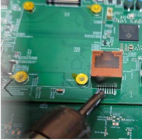
- Use a hot air gun to melt the solder on the pins.
- Lift the RJ45 connector from the PCB.
- Place the new component on the PCB. Be sure that it matches the PCB footprint.
- Solder the new component.
USB-A connector USB1/USB2/USB3/USB4/USB5
Repair the USB-A connector:

- Use a hot air gun to melt the solder on the pins from the bottom side..
- Lift the USB-A connector from the PCB.
- Place the new component on the PCB. Be sure that it matches the PCB footprint.
- Solder the new component.
Function test
After repair, be sure to confirm that all functions are working.
Table 4-1: Function test
| Test item | Operating description | Tool used |
| HDMI test | Confirm whether image displays and sound plays correctly on the monitor. | Computer or DVD player |
| DP test | Confirm whether image displays and sound plays correctly on the monitor. | Computer or DVD player |
| USB-C Alt-Mode | Confirm whether image displays and sound plays correctly on the monitor. | Computer or Notebook |
| USB-C PD Function | Confirm PDO/Charging working normally. | Notebook |
| USB Hub test | Confirm USB function of 3-USB Type-A and 1-USB Type-C working normally. | Computer or Notebook |
| Audio test | Change volume and balance to confirm whether volume is smooth and loud enough. | Sound bar |
| RJ45 test | Make sure your laptop can access the Internet through the monitor. | Notebook |
Support and troubleshooting
The following table lists possible problems, the possible cause or each problem, and the recommended solutions.
Table 4-2: Solving common problems
| Problem | Possible cause | Solution |
| Screen is blank or video is flashing. | Power cord is disconnected. | Connect the power cord. |
| Monitor is turned off. | Power the power button. NOTE: If pressing the Power button has no effect, press and hold the power button for 10 seconds to disable the Power button lockout feature. | |
| Video cable is improperly connected. | Connect the video cable properly. | |
| System is in Sleep mode. | Press any key on the keyboard or move the mouse to exit Sleep mode. | |
| Video card is incompatible. | Open the OSD menu and select the Input menu. Set Auto- Switch Input to Off and manually select the input. or Replace the video card or connect the video cable to one of the computer's onboard video sources. | |
| Image appears blurred, indistinct, or too dark. | Brightness is too low. | Open the OSD menu and select Brightness to adjust the brightness scale as needed. |
| Check Video Cable is displayed on screen. | Monitor video cable is disconnected. | Connect the appropriate video signal cable between the computer and monitor. Be sure that the computer power is off while you connect the video cable. |
| Input Signal Out of Range is displayed on screen. | Video resolution and/or refresh rate are set higher than what the monitor supports. | Change the settings to a supported setting. |
| The monitor does not enter into a low-power sleep state. | The monitor's power saving control is disabled. | Open the OSD menu and select Power, select Auto-Sleep Mode and set autosleep to On. |
| "OSD Lockout" is displayed. | The monitor's OSD lock function is enabled. | Press and hold the Left button for 10 seconds to disable the OSD lockout function. |
| "Power Button Lockout" is displayed. | The monitor's power button is locked. | Press and hold the Power button for 10 seconds to disable the power button lock function. |
| Monitor has trouble waking from Sleep mode | DisplayPort inputs: Set the DisplayPort hot-plug detection to Always Active. Power mode monitors: Set the hot-plug detection to Always Active to switch the monitor to Performance mode. | |
| Slow performance from USB | The monitor has a two-lane default for USB-C. On selected products, you can press the Joypad button to open the OSD menu, navigate to the USB Type-C configuration, and then select USB-C Video + USB 3.0 for data transfer prioritization. | |
| Lower refresh rate or color bits | Select USB-C Video + USB 2.0 for refresh rate/color bits prioritization. | |
| LAN connection drop | There is no upstream USB connection. | Check if the LAN driver version on the host PC is up to date. |
Important safety information
Carefully read the cautions and notes within this document to minimize the risk of personal injury to service personnel. The cautions and notes are not exhaustive. Proper service methods are important to the safe, reliable operation of equipment. Improper service methods can damage equipment.
The service procedures recommended and described in this service manual provide effective methods of performing service operations. Service engineers should have prior repair knowledge and experience as well as appropriate training for the product before performing service procedures.
- Be sure your working environment is dry and clean and meets all government safety requirements.
- Be sure that other persons are safe while you are servicing the product.
- Do not perform any action that can cause a hazard to the customer or make the product unsafe.
- Use proper safety devices to ensure your personal safety.
- Always use approved tools and test equipment for servicing.
- Never assume the product's power is disconnected from the main power supply. Check that it is disconnected before opening the product's cabinet.
- Modules containing electrical components are sensitive to electrostatic discharge (ESD). Follow ESD safety procedures while handling these parts.
- Some products contain more than one battery. Do not disassemble or expose a battery to high temperatures, such as throwing into fire, or the battery may explode.
- Refer to government requirements for battery recycling or disposal.
This information provides general service information for the monitor. Adherence to the procedures and precautions is essential for proper service.

Only trained service personnel who are familiar with this HP product should perform service or maintenance for it. Before performing any service or maintenance, personnel must read the important safety information.
You must disconnect the power cord from the power source before opening the monitor to prevent component damage.
Important service information and precautions
- Repair must be performed by professional service technicians in a repair center. End users should not perform these procedures.
- Please note during servicing that the primary side is the high voltage area.
- This monitor meets ROHS requirements. Be sure to use lead-free solder wire when soldering.
- If you must change a capacitor, be sure to match the polarity as printed on the PCB.
- If you must replace a capacitor, make sure the specification and part number match the BOM and location.
- If you must replace a capacitor, insert new parts carefully to avoid a short circuit caused by the near pin.
- Do not get the board wet. Water and moisture can cause a short circuit that causes malfunctions.
- To avoid damage, be sure to use lead-free solder.
- When soldering, work quickly to avoid overheating the circuit board.
- Keep the soldering iron tip clean and well tinned when replacing parts.
- After repair, perform a close inspection of the circuit board to confirm it is in good condition.
- After repair, perform a function test to confirm the power supply is working properly.
Documents / Resources
References
http://support.hp.com
http://www.hp.com/support
![www.digikey.com]() DigiKey - Electronic Components Distributor
DigiKey - Electronic Components Distributor![www.digikey.com]() DigiKey - Electronic Components Distributor
DigiKey - Electronic Components DistributorHP PartSurfer
![partsurfer.com]() http://partsurfer.com
http://partsurfer.com![www.eetgroup.com]() EET International
EET International

Download manual
Here you can download full pdf version of manual, it may contain additional safety instructions, warranty information, FCC rules, etc.
Advertisement


Need help?
Do you have a question about the 7 Pro Series and is the answer not in the manual?
Questions and answers