
Subscribe to Our Youtube Channel
Related Manuals for HP E243m


Summary of Contents for HP E243m
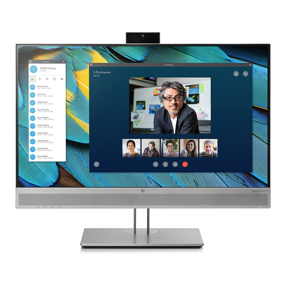
- Page 1 Maintenance and Service Guide E243m model SUMMARY This guide provides information about spare parts, removal and replacement of parts, diagnostic tests, problem troubleshooting, and more.
- Page 2 Devices, Inc. Bluetooth is a trademark owned sure to read “Important Safety Information”. by its proprietor and used by HP Inc. under license. NVIDIA is a trademark and/or registered trademark of NVIDIA Corporation in the U.S. and other countries. USB Type-C and USB-C are registered trademarks of USB Implementers Forum.
-
Page 3: Table Of Contents
Table of Contents 1 Getting started ................................1 Important safety information ..........................1 Important service information and precautions ....................1 RoHS (2002/95/EC) requirements .......................... 2 General descriptions .............................. 2 Firmware updates ..............................2 Before returning the repaired product to the customer ..................2 2 Monitor features ................................ -
Page 5: Getting Started
Getting started Read this chapter to learn about safety information and where to find additional HP resources. Important safety information Carefully read the cautions and notes within this document to minimize the risk of personal injury to service personnel. The cautions and notes are not exhaustive. Proper service methods are important to the safe, reliable operation of equipment. -
Page 6: Rohs (2002/95/Ec) Requirements
Level 2: Circuit board or standard parts replacement Firmware updates Firmware updates for the monitor are available at support.hp.com. If no firmware is posted, the monitor does not need a firmware update. Before returning the repaired product to the customer Perform an AC leakage current check on exposed metallic parts to be sure the product is safe to operate without the potential of electrical shock. -
Page 7: Monitor Features
Security cable slot provision on rear of monitor for optional security cable ● On-screen display (OSD) adjustments in several languages for easy setup and screen optimization ● HP Display Assistant software for adjusting monitor settings and enabling the theft deterrence ● features Cyberlink YouCam software ●... - Page 8 For safety and regulatory information, refer to the Product Notices provided in your documentation kit. To access the latest user guides or manuals for your product, go to http://www.hp.com/support and follow the instructions to find your product. Then select Manuals.
-
Page 9: Front Components
Front components To identify the components on the front of the monitor, use this illustration and table. Front of monitor showing location of controls Table 1-1: Front components and their descriptions 23.8–inch models Component Function Camera microphones Allow you to participate in a video conference. Camera light On: The camera is in use. - Page 10 23.8–inch models Component Function NOTE: You can reconfigure the Function buttons in the OSD menu to quickly select the most commonly used operations. See Assigning the function buttons on page 20 for more information. Power Press the button to turn the monitor on or off. When the monitor is on, the button power light above the power button is on.
-
Page 11: Rear Components
Rear components To identify the components on the rear of the monitor, use this illustration and table. Rear of monitor showing location connectors Table 1-2: Rear components and their descriptions 23.8–inch model Component Function USB ports (2) Connect USB devices. Audio-out (headphone) jack Connects optional powered stereo speakers, headphones, earbuds, a headset, or a television audio cable. -
Page 12: Locating The Serial Number And Product Number
The SPEC label (1) and Barcode label (2) are located on the rear of the monitor. The serial number and product number are located on a Safety label. You may need these numbers when contacting HP about the monitor model. - Page 13 Barcode label for India region...
-
Page 14: Illustrated Parts Catalog
To identify the monitor major components, use this illustration and table. Mechanical explosion Item Description PANEL ASSY, BEZEL, ASTROID, WBP, BOE-EC, E243m SCREW, I, CROSS, M3*4 ZN-CC SCREW, I, CROSS, T3*8, Zn ASSY, POP-UP MODULE, NEW, E243m Webcam ASSY, POP-UP MODULE, NEW, E243m... - Page 15 ASSY, STAND, FOR BOE, JARLLY, E243m MYLAR FOR PI, BACK, E243m, LP24QA BOLT, #4-40x11.8, Ni FOR D-SUB/DVI, C1018 MYLAR, CHASSIS MAIN, E233, SIDE 1 MYLAR, CHASSIS MAIN, E233, SIDE 2 IF BD PWR BD MYLAR FOR PI, FRONT, E243m, LP24QA...
-
Page 16: How To Order Parts
How to order parts The HP authorized repair center can purchase the power board from HP. Power board Manufacturer part Remark Description HP spare part number number PCBA,PI/BD,W/SPK,LP24QA- M74385-001 790NQ1400D00H01 D18/E243m/HF PCBA,PI/BD,W/SPK,LP24QA- M74386-001 790NQ1400800H01 818/E243m/HF PCBA,PI/BD,W/SPK,LP24QA- M74387-001 790NQ1400A00H01 A18/E243m/HF PCBA,PI/BD,W/SPK,LP24QA-... - Page 17 You can purchase cables from the HP part store at https://partsurfer.hp.com/Search.aspx. NOTE: HP continually improves and changes product parts. For complete and current information about supported parts for your computer, go to http://partsurfer.com, select your country or region, and then follow the on-screen instructions.
-
Page 18: Removal And Replacement Procedures
Removal and replacement procedures Adherence to these procedures and precautions is essential for proper service. Preparation for disassembly Use this information to properly prepare to disassemble and reassemble the monitor. 1) Read the “Important safety information” and “Important service information and precautions” sections in the “Getting started”... - Page 19 1) Remove four screw from the rear case. Remove screw from rear cover 2) Insert the scraper bar tool into the gap between the middle frame and rear case, and then rotate. The hook opens. Repeat the steps. Be careful with four corners DO NOT move away rear case immediately. Separate rear cover and middle frame step Separate rear cover and middle frame step 3) Hang up rear case, disconnect the webcam control cable and then take away rear case.
- Page 20 Webcam cable separate step 4) Peel off tapes, disconnect the speaker cables unfix six screws and take out the speakers. Speaker separate step 5) Unscrew the side USB cover, pull it rightward and reverse, then disconnect the cable. USB side chassis separate step 6) Peel the foils off, disconnect the backlight cable and LVDS cable.
- Page 21 8) Peel all tapes off the metal chassis, take out mylar sheet, unfix two bolts and seven pan head screws. PCBA and Chassis separate step 9) Take out IF BD and Power BD, disconnect all cables. Take out all cables from PCBA 10) Unscrew USB board and take it out.
- Page 22 Separate webcam board module step 14) Lift the webcam lens and insert the scraper bar, then unhook it from the module. Separate webcam module step 15) Unscrew two PW screws and take it out. Unlock three flat screws, peel off conductive fabric, insert the scraper bar and separate the two plastic parts.
-
Page 23: Power Board
Prepare the monitor for disassembly. See Preparation for disassembly on page 14. ▲ Remove the power board: 1) The HP E243m power board connector position is as follows: Power Board location showing of connector CN4 Foxconn P/N: 3406BA900-39U-H CN851 Foxconn P/N: 35104C700-39U-H... - Page 24 Part number location of power board 3) Remove the backlight cable and main board. Remove the backlight cable and main board.
-
Page 25: Connector Repair
Connector repair This procedure includes HDMI, Display Port, VGA, audio in, headphone, USB upstream and USB connectors. The connectors are on the main board (board part number 790NQ1300***H01) and USB side board (board part number 790NQ0300***H0*). The connectors’ identifiers are as follows: Connector Location HDMI... -
Page 26: Audio Connector Cn50
Connector location showing of USB side board Before repairing connectors, follow these steps: Prepare the monitor for disassembly. See Preparation for disassembly on page 14. ▲ Audio connector CN50 Repair the audio connector: 1) Use a hot air gun to melt the solder on the pins. Pin solder with soldering iron and absorber. You can gently push down with the soldering iron once everything is molten to move the CN502 out of the through holes. -
Page 27: Vga Connector Cn201
1) Use a soldering iron and a desoldering pump to remove as much solder as possible from the pin. HDMI connector repairing 2) Use a hot air gun to melt the solder on the pins. HDMI connector repairing 3) Lift the J2 connector from the PCB. 4) Place the new component on the PCB. -
Page 28: Usb Upstream Connector Cn602
3) Place the new component on the PCB. Be sure that it matches the PCB footprint. 4) Solder the new component. USB upstream connector CN602 Repair the USB upstream connector: 1) Use a hot air gun to melt the solder on the pins. Pin solder with soldering iron and absorber. You can gently push down with the soldering iron once everything is molten to move the CN602 out of the through holes. -
Page 29: Headphone Connector Cn101
Headphone connector CN101 Repair the Headphone connector: 1) Use a hot air gun to heat the bottom side of PCB below the headphone connector. Headphone connector repairing 2) Lift the CN101 connector from the PCB. 3) Place the new component on the PCB. Be sure that it matches the PCB footprint. 4) Solder the new component. - Page 30 Table 4-2: Solving common problems Problem Possible cause Solution Screen is blank or Power cord is disconnected. Connect the power cord. video is flashing. Monitor is off. Power the power button. NOTE: If pressing the Power button has no effect, press and hold the power button for 10 seconds to disable the Power button lockout...
-
Page 31: Index
Index components preparation for disassembly, 12 front, 5 RC removal, 12 rear, 6 rear components, 6 connector repair, 17 removal DisplayPort connector location, 6 power board, 15 features, 4 RC, 12 firmware updates, 2 xxxx, 20 front components, 5 removal and replacement procedures, 12 function button locations, 5 returning to customer, 2 function test, 20...
Need help?
Do you have a question about the E243m and is the answer not in the manual?
Questions and answers