Table of Contents
Advertisement
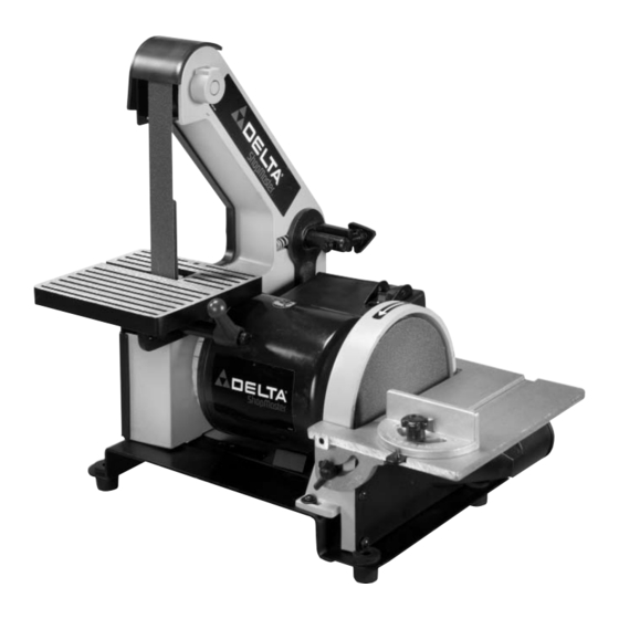
1" Belt / 5" Disc
Sander
(Model SA150)
PART NO. 905593 - 05-31-02
Copyright © 2002 Delta Machinery
To learn more about DELTA MACHINERY
ESPAÑOL: PÁGINA 13
visit our website at: www.deltamachinery.com.
For Parts, Service, Warranty or other Assistance,
1-800-223-7278 (
1-800-463-3582).
please call
In Canada call
Advertisement
Table of Contents

Related Manuals for Delta ShopMaster SA150


Summary of Contents for Delta ShopMaster SA150
- Page 1 1" Belt / 5" Disc Sander (Model SA150) PART NO. 905593 - 05-31-02 Copyright © 2002 Delta Machinery To learn more about DELTA MACHINERY ESPAÑOL: PÁGINA 13 visit our website at: www.deltamachinery.com. For Parts, Service, Warranty or other Assistance, 1-800-223-7278 ( 1-800-463-3582).
-
Page 2: General Safety Rules
If you have any questions relative to a particular application, DO NOT use the machine until you have first contacted Delta to determine if it can or should be performed on the product. -
Page 3: Additional Safety Rules For Belt / Disc Sanders
“ON.” 24. NEVER perform layout, assembly, or set-up work on the tables while the sander is operating. 25. ALWAYS turn the machine “OFF” and disconnect the cord from the power source before installing or removing accessories. -
Page 4: Motor Specifications
A separate electrical circuit should be used for your machines. This circuit should not be less than #12 wire and should be protected with a 20 Amp time lag fuse. If an extension cord is used, use only 3-wire extension cords which have 3- prong grounding type plugs and matching receptacle which will accept the machine’s plug. -
Page 5: Extension Cords
OPERATING INSTRUCTIONS FOREWORD The Delta ShopMaster Model SA150 Belt/Disc Sander is a handy machine for sanding wood, metal, plastic, or ceramic workpieces. This machine incorporates a 1" belt sander and a 5" disc sander, and uses an induction motor for long- lasting performance. -
Page 6: Assembly
(F), spring (E), and handle (D) from locking stud (C). 3. Place table (G) Fig. 3, on sander by inserting belt (H) and platen (I) through opening (J) in table, as shown. -
Page 7: Fastening Sander To Supporting Surface
(B), adjust the table so that there is a maximum 1/16" between the work table and the disc (see the section “DISC TABLE ADJUSTMENTS”). FASTENING SANDER TO SUPPORTING SURFACE IMPORTANT: If the machine has a tendency to tip over or to walk on the supporting surface, the machine must be secured. -
Page 8: Operating Controls And Adjustments
STOPPING SANDER The switch (A) Fig. 15 is located on the top of the switch box. To start the sander, move the switch forward to the “ON” position. To stop the sander, move the switch back to the “OFF” position. -
Page 9: Disc Table Adjustments
The platen (A) Fig. 22, is constructed of heavy steel to properly support the work. To adjust, remove the belt sander table (see the section “BELT SANDER TABLE” in assembly). Loosen the two screws (B) Fig. 22, that fasten the bottom of the platen to the frame, adjust the platen (A), so that it is almost touching the back of the sanding belt, and tighten the two screws (B). -
Page 10: Changing Sanding Disc
CHANGING ABRASIVE BELT 1. DISCONNECT MACHINE FROM POWER SOURCE. 2. Remove lock knob (A) Fig. 23, and remove side cover (B). 3. Depress tracking knob (C) Fig. 24, to release belt tension and remove belt (D) from the three wheels (E), as shown. -
Page 11: Accessories
(B), moving miter gauge head to the desired angle and tightening lock knob (B). A complete line of accessories is available from your Delta Supplier, Porter-Cable • Delta Factory Service Centers, and Delta Authorized Service Stations. Please visit our Web Site for the name of your nearest supplier. -
Page 12: Parts, Service Or Warranty Assistance
1-800-223-7278 (In Canada call 1-800-463-3582). Delta will repair or replace, at its expense and at its option, any Delta machine, machine part, or machine accessory which in normal use has proven to be defective in workmanship or material, provided that the customer returns the product prepaid to a Delta factory service center or authorized service station with proof of purchase of the product within two years and provides Delta with reasonable opportunity to verify the alleged defect by inspection.