Table of Contents
Advertisement
Available languages
Available languages
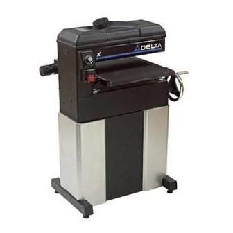
18" x 36" Drum Sander
Ponceuse à tambour
de 457 mm x 914 mm
(18 po x 36 po)
Lijadora de tambor
de 457 mm x 914 mm
(18" x 36")
Français (21)
Español (40)
Instruction manual
Manuel d'utilisation
Manual de instrucciones
www.deltaportercable.com
TO REDUCE THE RISK OF INJURY,
USER MUST READ INSTRUCTION
MANUAL BEFORE OPERATING PRODUCT.
PARA REDUCIR EL RIESGO
DE LESIONES, EL USUARIO
DEBE LEER EL MANUAL DE INSTRUCCIONES ANTES
DE OPERAR EL PRODUCTO
AFIN DE RÉDUIRE LE
RISQUE DE BLESSURES,
L'UTILISATEUR DOIT LIRE LE MODE D'EMPLOI
AVANT D'UTILISER LE PRODUIT.
31-260X
Advertisement
Table of Contents

Subscribe to Our Youtube Channel
Related Manuals for Delta 31-260X


Summary of Contents for Delta 31-260X
- Page 1 MANUAL BEFORE OPERATING PRODUCT. PARA REDUCIR EL RIESGO DE LESIONES, EL USUARIO DEBE LEER EL MANUAL DE INSTRUCCIONES ANTES DE OPERAR EL PRODUCTO AFIN DE RÉDUIRE LE RISQUE DE BLESSURES, L’UTILISATEUR DOIT LIRE LE MODE D’EMPLOI AVANT D’UTILISER LE PRODUIT. 31-260X...
-
Page 2: Table Of Contents
IMPORTANT SAFETY INSTRUCTIONS ...2 SAFETY GUIDELINES - DEFINITIONS ...2 GENERAL SAFETY RULES ...3 ADDITIONAL SPECIFIC SAFETY RULES ...4 FUNCTIONAL DESCRIPTION ...6 CARTON CONTENTS ...6 ASSEMBLY ...7 OPERATION ...9 IMPORTANT SAFETY INSTRUCTIONS Read and understand all warnings and operating instructions before using any tool or equipment. -
Page 3: General Safety Rules
GENERAL SAFETY RULES Failure to follow these rules may result in serious personal injury. FOR YOUR OWN SAFETY, READ THE INSTRUCTION MANUAL BEFORE OPERATING THE MACHINE. Learning the machine’s application, limitations, and specific hazards will greatly minimize the possibility of accidents and injury. WEAR EYE AND HEARING PROTECTION. -
Page 4: Additional Specific Safety Rules
ADDITIONAL SPECIFIC SAFETY RULES Failure to follow these rules may result in serious personal injury. DO NOT OPERATE THIS TOOL UNTIL it is assembled and installed according to the instructions. OBTAIN ADVICE from your supervisor, instructor, or another qualified person if you are not familiar with the operation of this tool. - Page 5 All grounded, cord-connected machines: In the event of a malfunction or breakdown, grounding provides a path of least resistance for electric current to reduce the risk of electric shock. This machine is equipped with an electric cord having an equipment-grounding conductor and a grounding plug.
-
Page 6: Functional Description
FOREWORD The Delta Model 31-260X is an 18" x 36" drum sander with a two-speed drum. Its single-piece frame and cast-iron table construction provides accuracy, stability, and easy adjustments. This unit can be fitted with an optional outboard shaft that accommodates an accessory pneumatic drum for contour sanding. -
Page 7: Assembly
Attach the center piece (E) to the rest of the assembly with M8-20 Carriage Bolts and Nuts. Tighten all hardware securely. Fig. 1A HOW TO ATTACH THE SANDER TO THE STAND This machine is heavy. Use two or more people when lifting. Place the machine on its end (Fig. 2), resting on the two wood blocks (not supplied). - Page 8 HOW TO ATTACH THE HANDWHEEL Place the handwheel (A) Fig. 4 on shaft (B). Align the set screw with the drilled recess in the shaft. Fasten the handwheel to the shaft by tightening the set screw (C) Fig. 5. Make sure that the set screw contacts the flat of the shaft and not the O.D.
-
Page 9: Operating Controls And Adjustments
HOW TO ATTACH THE SA FEED INDICATOR Disconnect machine from power source. Position the SA indicator on the table as indicated in (A) Fig. 11A. Place the #10 washer (B) Fig. 11B on the indicator bolt. Securely fasten the SA indicator to the table with the bolt and washer. To fine tune, loosen the screw (C) Fig. - Page 10 HOW TO RAISE THE TABLE To raise the feed table, turn the handwheel (A) Fig. 15 counter- clockwise. To lower the feed table, turn hand-wheel clockwise. NOTE: Each 1/4 turn of handwheel (A) increases or decreases the height of the table by 1/64". HOW TO CHECK AND ADJUST THE FEED BELT TRACKING AND TENSION IMPORTANT: Read this complete section be fore making any adjustments to belt track ing or tension.
- Page 11 Fig. 19 HOW TO SET THE HEIGHT SCALE Run a piece of lumber through the drum sander (Fig. 22) to finish one side of the board. Use a square (A) Fig. 23 to measure the thickness of the lumber. Loosen the bolt (B) Fig. 24. Move scale up or down until the cursor shows the exact board thickness that was measured in STEP 2.
- Page 12 HOW TO CHANGE THE DRUM SPEEDS AND REPLACE THE DRIVE BELT The drum sander has two drum speeds - 2210 SFM or 3300 SFM. To change the sanding drum speeds or to replace the drive belt: Disconnect machine from power source.
- Page 13 HOW TO REMOVE AND REPLACE THE FEED BELT Disconnect machine from power source. Disconnect the DC Motor Quick Connect. (Fig. 31). Use a 1/4" hex wrench to remove the four table mounting bolts, lockwashers and flange nuts , two of which are shown at (A) Fig.
-
Page 14: Frequently Asked Questions
Stock can be removed more quickly by using a fast speed, but the machine works much harder, and the wood is left with a rougher finish. Slowing the speed will lighten the load of the sander, and make the finish better, but it will increase the sanding time. - Page 15 The sander will accept more than one board at a time if the total width is 16" or less and are the same thickness. Pass the first board. When it reaches the rear pressure roller, start another board on the other side of the table. Depending on the width, several boards can go through the sander at one time.
-
Page 16: How Do I Get Started
Use different wood types and different widths. 2. To see how the sander works, measure the thickness of your stock. Set the table height to that thickness and then lower it 1/4 turn. Turn the drum switch "ON" and then turn the table feed belt speed to 50%. If the drum does not contact the stock, raise the table height slowly while feeding the stock through, until you see that it is sanding. -
Page 17: Step 1 - Timing Belt Tension
STEP 1 - TIMING BELT TENSION 1. If the timing belt is too tight, the table will be difficult to move. A loose timing belt may cause the belt to jump a tooth on the timing gear. Deflection in the middle of the long span should be 2-3 lbs. 2. -
Page 18: Troubleshooting
STEP 3 - CHECKING THE LOCK NUT ADJUSTMENT A 3/4" locknut is on the base of three of the elevating bolts (B) Fig. 42. Under this nut is a thrust washer, thrust bearing, and another thrust washer (T) Fig. 42. Note: The front left elevating bolt uses a jam nut that should remain tight. -
Page 19: Keep Machine Clean
BRUSH INSPECTION AND REPLACEMENT Before inspecting brushes, disconnect the machine from the power source. Fig. 43 Fig. 44 Brush life varies. Check the brushes after the first 50 hours of use for a new machine or periodically after a new set of brushes has been installed. -
Page 20: Free Warning Label Replacement
FREE WARNING LABEL REPLACEMENT If your warning labels become illegible or are missing, call 1-800-223-7278 for a free replacement. SERVICE AND REPAIRS All quality tools will eventually require servicing and/or replacement of parts. For information about Delta Machinery, its factory-owned branches, or an Authorized Warranty Service Center, visit our website at www.deltamachinery.com or call our Customer Care Center at 1-800-223-7278. -
Page 21: Mesures De Sécurité - Définitions
LES INSTRUCTIONS IMPORTANTES DE SURETE Lire et comprendre toutes instructions d'avertissements et opération avant d'utiliser n'importe quel outil ou n'importe quel équipement. En utilisant les outils ou l'équipement, les précautions de sûreté fondamentales toujours devraient être suivies pour réduire le risque de blessure personnelle. -
Page 22: Règles De Sécurité Générales
RÈGLES DE SÉCURITÉ GÉNÉRALES POUR SA SÉCURITÉ PERSONNELLE, LIRE LA NOTICE D’UTILISATION, AVANT DE METTRE LA MACHINE EN MARCHE, et pour aussi apprendre l’application et les limites de la machine ainsi que les risques qui lui sont particuliers ainsi, les possibilités d’accident et de blessures seront beaucoup réduites. - Page 23 RÈGLES SPÉCIFIQUES ADDITIONNELLES DE SÛRETÉ NE PAS FAIRE FONCTIONNER CET OUTIL AVANT qu’il ne soit assemblé et installé conformément à ces directives. CONSULTER le superviseur, instructeur, ou tout autre personne qualifiée SI VOUS N’ÊTES PAS FAMILIARISÉ AVEC LE FONCTIONNEMENT DE L’OUTIL. SUIVRE TOUS LES CODES DE CÂBLAGE et les connexions électriques recommandées.
-
Page 24: Cordon De Rallonge
Toutes les machines avec cordon mis à la terre: Dans l’éventualité d’un mauvais fonctionnement ou d’unepanne, la mise à la terre fournit un trajet de moindre résistance permettant de réduire le risque de décharge électrique. Cette machine est dotée d’un cordon électrique possédant unconducteur de mise à... -
Page 25: Description Fonctionnelle
AVANT-PROPOS Le modèle Delta 31-260X est une ponceuse à tambour de 457,2 mm x 914,4 mm (18 po x 36 po) avec un tambour à deux vitesses. Sa construction à cadre monobloc et à table en fonte assure précision, stabilité et des réglages faciles. Cet appareil peut être équipé... - Page 26 Attacher la pièce centrale (D) au reste de l’assemblage. Serrer fermement tout le matériel. Fig. 1A HOW TO ATTACH THE SANDER TO THE STAND This machine is heavy. Use two or more people when lifting. Déposer l’appareil sur son côté (fig. 2), appuyé sur deux blocs de bois (non fournis).
- Page 27 FIXATION DU VOLANT Placer le volant (A), Fig. 4, sur l’arbre (B). Aligner la vis de calage avec le creux aménagé dans l’arbre. Fixer le volant à l’arbre en serrant la vis de calage (C), Fig. 5. S’assurer que la vis de calage s’appuie contre la partie plate de l’arbre et non contre la surface extérieure.
- Page 28 FIXATION DE L’INDICATEUR D’ALIMENTATION « SA » Disconnect machine from power source. Positionner l’indicateur « SA » sur la table comme indiqué en (A), fig. 11A. Enfiler la rondelle nº 10 (B), fig. 11B, sur le boulon index. Fixer solidement l’indicateur « SA » à la table au moyen du boulon et de la rondelle. Pour le réglage fin, desserrer la vis (C), fig.
- Page 29 ÉLÉVATION DE LA TABLE Pour lever la table d’alimentation, tourner le volant (A), Fig. 15, dans le sens antihoraire. Pour abaisser la table d’alimentation, tourner le volant dans le sens horaire. REMARQUE : chaque 1/4 de tour du volant (A) accroît ou réduit la hauteur de la table de 0,40 mm (1/64 po).
- Page 30 PROTECTION CONTRE LES SURCHARGES DU MOTEUR DU TAMBOUR Le moteur du tambour est doté d’un bouton de réinitialisation du re- lais de surcharge. Si le moteur refuse de démarrer en raison d’une surcharge ou d’une faible tension, mettre les deux interrupteurs sur arrêt (OFF).
- Page 31 MODIFICATION DES VITESSES DE TAMBOUR ET REMPLACEMENT DE LA COURROIE D’ENTRAÎNEMENT La ponceuse à tambour offre deux vitesses de tambour : 205,3 m²/min ou 306,6 m²/min (2 210 pi²/min ou 3 300 pi²/min). Pour modifier les vitesses du cylindre de contact ou pour remplacer la courroie d’entraînement : Débrancher la machine de la source d’alimentation.
- Page 32 RETRAIT ET REMPLACEMENT DE LA COURROIE D’ALIMENTATION Débrancher la machine de la source d’alimentation. Débrancher le raccord de branchement rapide du moteur c.c. (Fig. 31.) Utiliser une clé hexagonale de 6,3 mm (1/4 po) pour retirer les quatre boulons de montage, rondelles de blocage et écrous à embase de la table, dont deux sont illustrés à...
- Page 33 INSTALLATION EN VUE DU DÉPOUSSIÉRAGE Le capot du tambour comporte une goulotte de poussière au diamètre extérieur de 101,6 mm (4 po) (A), Fig. 36, qui se raccorde à un système de dépoussiérage. Ne jamais faire fonctionner cet appareil sans y avoir relié un système de dépoussiérage.
- Page 34 QUELLES SONT LES RECOMMANDATIONS POUR LE DÉPOUSSIÉRAGE Il est recommandé d’utiliser un système de dépoussiérage présentant une capacité minimale de 11 à 17 m3/min (400 à 600 pi3/min). COMMENT PUIS-JE PONCER DES CADRES EN FAÇADE ET DES PORTES À PANNEAUX EN RELIEF Certaines portes ont des planches dont le grain présente un tracé...
- Page 35 COMMENT PUIS-JE PONCER DES PLANCHES DONT LA LARGEUR DÉPASSE 457 mm (18 po)? IMPORTANT : au moment de poncer des pièces dont la largeur excède 457 mm (18 po), si le tambour n’est pas parallèle à la table, il peut se produire un décalage ou un trait. Il est préférable de régler le côté ouvert de quelques millièmes de cm (po) de plus pour permettre le ponçage d’un bombement que d’une rainure (consulter la Fig.
- Page 36 ÉTAPE 1 : TENSION DE LA COURROIE CRANTÉE Si la courroie crantée est trop serrée, la table bouge difficilement. Une courroie crantée lâche peut être portée à sauter une dent sur l’engrenage de distribution. La déflexion au milieu du long segment devrait être de 0,91 à 1,36 kg (2 à 3 lb). Pour régler la tension, situer l’un des rouleaux tendeurs de la courroie crantée sous l’extrémité...
-
Page 37: Depannage
ÉTAPE 3 : VÉRIFICATION DE L’AJUSTEMENT DU CONTRE-ÉCROU Un contre-écrou de 19 mm (3/4 po) se trouve à la base de trois des boulons d’élévation (B), Fig. 42. Sous cet écrou, il y a une rondelle de butée, un palier de butée et une autre rondelle de butée (T), Fig. - Page 38 INSPECTION ET REMPLACEMENT DES BROSSES Avant d’inspecter les brosses, débrancher l’appareil de la source d’alimentation. Fig. 43 La durée de vie des brosses est variable. Vérifier les brosses après les 50 premières heures d’utilisation de l’appareil ou péri- odiquement après l’installation de nouvelles brosses. Une fois la première vérification effectuée, examiner les brosses toutes les 10 heures d’utilisation (environ), et ce, jusqu’à...
-
Page 39: Entretien Et Réparation
REMPLACEMENT GRATUIT DE L'ÉTIQUETTE Si vos étiquettes d'avertissement deviennent illisibles ou sont manquantes, composez le 1-800-223-7278 pour obtenir une étiquette de remplacement gratuite. ENTRETIEN ET RÉPARATION Tous les outils de qualité finissent par demander un entretien ou un changement de pièce. Pour de plus amples renseignements à... -
Page 40: Español
INSTRUCCIONES DE SEGURIDAD IMPORTANTES Lea y entienda todas advertencias y las instrucciones operadoras antes de utilizar cualquier instrumento o el equipo. Cuando se usa instrumentos o equipo, las precauciones básicas de la seguridad siempre se deben seguir para reducir el riesgo de la herida personal. La operación impropia, la conservación o la modificación de instrumentos o equipo podrían tener como resultado el daño grave de la herida y la propiedad. -
Page 41: Normas Generales De Seguridad
NORMAS GENERALES DE SEGURIDAD PARA SU PROPIA SEGURIDAD, LEA EL MANUAL DE INSTRUCCIONES ANTES DE UTILIZAR LA MÁQUINA. Al aprender la aplicación, las limitaciones y los peligros específicos de la máquina, se minimizará enormemente la posibilidad de accidentes y lesiones. USE PROTECCIÓN DE LOS OJOS Y DE LA AUDICIÓN. - Page 42 NORMAS ESPECÍFICAS ADICIONALES DE SEGURIDAD Si no se siguen estas normas, el resultado podría ser lesiones personales graves. NO OPERE ESTA MÁQUINA HASTA QUE esté armada e instalada según las instrucciones. SOLICITE EL ASesoramiento de su suPErvisor, instructor o alguna persona caLificada si no está familiarizado con el funcionamiento de esta herramienta.
-
Page 43: Cordones De Extensión
Todas las máquinas conectadas con cordón conectadas a tierra: En caso de mal funcionamiento o avería, la conexión a tierra proporciona una ruta de resistencia mínima para la corriente eléctrica, con el fin de reducir el riesgo de descargas eléctricas. Esta máquina está equipada con un cordón eléctrico que tiene un conductor de conexión a tierra del equipo y un enchufe de conexión a tierra. -
Page 44: Descripción Funcional
PROLOGO El modelo Delta 31-260X es una lijadora de tambor de 457 mm x 914 mm (18" x 36") con un tambor de dos velocidades. Su estructura de una sola pieza y su construcción con mesa de hierro fundido proporciona precisión, estabilidad y facilita los ajustes. A esta unidad se le puede anexar un eje exterior opcional al que se puede adaptar un tambor neumático accesorio para lijar contornos. - Page 45 Para su propia seguridad, no conecte la maquina a la fuente de energia hasta que la maquina haya sido ensamblada por completo y usted haya leido y entendido completamente el manual del propietario. HERRAMIENTAS DE ENSAMBLAJE REQUERIDAS ESTIMACIÓN DEL TIEMPO DE ENSAMBLAJE La asamblea para esta máquina es más o menos 2 horas.
- Page 46 CÓMO INSTALAR EL VOLANTE Coloque el volante (A) Fig. 4 en el eje (B). Alinee el tornillo de sujeción con la cavidad perforada en el eje. Asegure el volante al eje con el tornillo de sujeción (C) Fig. 5. Asegúrese de que el tornillo de sujeción haga contacto con la parte plana del eje y no el diámetro externo del eje.
-
Page 47: Operación
CÓMO CONECTAR EL INDICADOR DE ALIMENTACIÓN SA Disconnect machine from power source. Coloque el indicador SA en la mesa como se indica en la (A) Fig. 11A. Coloque la arandela n.º 10 (B) Fig. 11B en el perno del indicador. Asegure firmemente el indicador SA a la mesa con el perno y la arandela. - Page 48 CÓMO ELEVAR LA MESA Para elevar la mesa de alimentación, gire el volante (A) Fig. 15 en sen- tido contrario a las agujas del reloj. Para bajar la mesa de alimentación, gire el volante en el sentido de las agujas del reloj. NOTA: Cada cuarto de vuelta del volante (A), la mesa aumenta o dis- minuye la altura en 0,4 mm (1/64").
- Page 49 PROTECCIÓN CONTRA SOBRECARGA DEL MOTOR DEL TAMBOR El motor del tambor tiene un relé de reinicio por sobrecarga. Si el motor no enciende debido a una sobrecarga o porque el voltaje es bajo, gire ambos interruptores a la posición de apagado (OFF). Deje que el motor se enfríe de 3 a 5 minutos y después pre- sione el botón de reinicio (A) Fig.
- Page 50 CÓMO CAMBIAR LAS VELOCIDADES DEL TAMBOR Y REEMPLAZAR LA BANDA IMPULSORA La lijadora de tambor tiene dos velocidades del tambor: 674 ó 1.006 metros de superficie (2.210 ó 3.300 pies de superficie) por minuto. Para cambiar las velocidades del tambor o para reemplazar la banda impulsora: Desconecte la máquina de la fuente de energía.
- Page 51 CÓMO QUITAR Y REEMPLAZAR LA BANDA DE ALIMENTACIÓN Desconecte la máquina de la fuente de energía. Desconecte el motor de CC Quick Connect. (Fig. 31). Utilice una llave hexagonal de 6,4 mm (1/4") para extraer los cuatro pernos de montaje de la mesa, las arandelas de bloqueo y las tuercas de brida, dos de las cuales se muestran en (A) Fig.
- Page 52 CÓMO CONFIGURAR LA RECOLECCIÓN DE POLVO La cubierta del tambor tiene un conducto para polvo de 102 mm (4") de diámetro exterior (A) Fig. 36 que se conecta a un sistema de recolección de polvo. Nunca opere esta máquina sin un sistema de recolección de polvo instalado.
- Page 53 ¿QUÉ SE RECOMIENDA PARA LA RECOLECCIÓN DE POLVO? ¿CÓMO LIJO LOS MARCOS DELANTEROS y LAS PUERTAS CON PANELES EN RELIEVE? 1. Algunas puertas tienen tablas con el grano que corre a 90 grados. Recomendamos utilizar un papel de grano más fino, remover la cantidad mínima de material y disminuir el nivel de alimentación.
- Page 54 ¿CÓMO LIJO TABLAS MÁS ANCHAS QUE 457 MM (18")? IMPORTANTE: Cuando lije piezas más anchas que 457 mm (18"), si el tambor no está paralelo a la mesa se producirá un salto o una línea. Es mejor colocar el lado abierto a unos pocos milésimos de pulgada más abierto para permitir el lijado de una corona más que el de una ranura.(Consulte Fig.
- Page 55 PASO 1: TENSIÓN DE LA BANDA DE DISTRIBUCIÓN Si la banda de distribución está demasiado ajustada, se hará difícil mover la mesa. Una banda de distribución suelta puede hacer que la banda saltee un diente en el engranaje de distribución. La desviación en el medio del alcance largo debe ser de 2 a 3 libras.
-
Page 56: Localizacion De Fallas
PASO 3: COMPROBACIÓN DEL AJUSTE DE LA TUERCA DE SEGURIDAD Hay una tuerca de seguridad de 19 mm (3/4") en la base de tres de los pernos de elevación (B) Fig. 42. Debajo de esta tuerca, hay una arandela de empuje, un cojinete de empuje y otra arandela de empuje (T) Fig. -
Page 57: Mantenimiento
INSPECCIÓN Y REEMPLAZO DE LOS CEPILLOS Antes de inspeccionar los cepillos, desconecte la máquina de la fuente de alimentación. Fig. 43 La vida útil de los cepillos es variable. Controle los cepillos después de las primeras 50 horas de uso en una máquina nueva o perió- dicamente después de que se ha instalado un juego de cepillos nuevos. -
Page 58: Service And Repairs
FREE WARNING LABEL REPLACEMENT If your warning labels become illegible or are missing, call 1-800-223-7278 for a free replacement. SERVICE AND REPAIRS All quality tools will eventually require servicing and/or replacement of parts. For information about Delta Machinery, its factory-owned branches, or an Authorized Warranty Service Center, visit our website at www.deltamachinery.com or call our Customer Care Center at 1-800-223-7278. -
Page 59: Póliza De Garantía
IDENTIFICACIÓN DELPRODUCTO: Sello o firma del Distribuidor.Nombre del producto: _______________________ Mod./Cat.: ________________________Marca: ________ _______________________ Núm. de serie:________________________(Datos para ser llenados por el distribuidor)Fecha de compra y/o entrega del producto: _______________________________________Nombre y domicilio del distribuidor donde se adquirió el producto:__ ________________________________________________________________________Este producto está garantizado por un año a partir de la fecha de entrega, contra cualquierdefecto en su funcionamiento, así... - Page 60 The following are trademarks for one or more Porter-Cable and Delta products: Les marques suivantes sont des marques de commerce se rapportant à un ou plusieurs produits Porter-Cable ou Delta : Las siguientes son marcas comerciales para uno o más productos de Porter-Cable y Delta: 2 BY 4 ®...
Need help?
Do you have a question about the 31-260X and is the answer not in the manual?
Questions and answers