Table of Contents
Advertisement
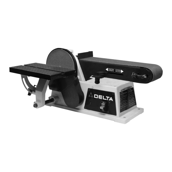
4" Belt / 6" Disc Sander
(Model 31-460)
PART NO. 900465 (0112)
Copyright © 2001 Delta Machinery
To learn more about DELTA MACHINERY
ESPAÑOL: PÁGINA 21
visit our website at: www.deltamachinery.com.
For Parts, Service, Warranty or other Assistance,
1-800-223-7278 (
1-800-463-3582).
please call
In Canada call
Advertisement
Table of Contents

Related Manuals for Delta 31-460


Summary of Contents for Delta 31-460
- Page 1 4" Belt / 6" Disc Sander (Model 31-460) PART NO. 900465 (0112) Copyright © 2001 Delta Machinery To learn more about DELTA MACHINERY ESPAÑOL: PÁGINA 21 visit our website at: www.deltamachinery.com. For Parts, Service, Warranty or other Assistance, 1-800-223-7278 ( 1-800-463-3582).
-
Page 2: General Safety Rules
If you have any questions relative to a particular application, DO NOT use the machine until you have first contacted Delta to determine if it can or should be performed on the product. -
Page 3: Additional Safety Rules For Belt / Disc Sanders
27. THE USE of attachments and accessories not 12. ALWAYS hold the workpiece firmly on the table recommended by Delta may result in the risk of injuries. when sanding on the disc. 28. ADDITIONAL INFORMATION regarding the safe 13. -
Page 4: Power Connections
POWER CONNECTIONS A separate electrical circuit should be used for your machines. This circuit should not be less than #12 wire and should be protected with a 20 Amp time lag fuse. If an extension cord is used, use only 3-wire extension cords which have 3- prong grounding type plugs and matching receptacle which will accept the machine’s plug. -
Page 5: Extension Cords
FOREWORD The Delta Model 31-460 is a 4" Belt; 6" Disc Sander and comes equipped with; 1/3 hp 120 Volt Single Phase Induction Motor, tilting table, miter gage, backstop, 4" x 36" 60 grit sanding belt and 6" 60 grit sanding disc. The tilting aluminum table can be mounted for use on either the belt or disc unit. -
Page 6: Adjusting Belt Tension
ASSEMBLY INSTRUCTIONS WARNING: FOR YOUR OWN SAFETY, DO NOT CONNECT THE SANDER TO THE POWER SOURCE UNTIL THE MACHINE IS COMPLETELY ASSEMBLED AND YOU HAVE READ AND UNDERSTOOD THE ENTIRE OWNERS MANUAL. ADJUSTING BELT TENSION Your sander was shipped from the factory with the drive belt (A) Fig. -
Page 7: Assembling Belt And Pulley Guard
ASSEMBLING BELT AND PULLEY GUARD Assemble the belt and pulley guard (A) Fig. 5, to the machine base using the two 1-3/16" (30mm) long screws (B), as shown. Fig. 5 ASSEMBLING SANDING DISC PLATE Thread the 1/4" long set screw (A) Fig. 6, into the tapped hole on hub of sanding disc plate. -
Page 8: Assembling Sanding Disc
ASSEMBLING SANDING DISC Make sure sanding disc plate (A) Fig. 9, is clean. Peel backing from sanding disc and press disc (B) firmly into position all the way around the sanding plate, as shown in Fig. 9. Fig. 9 ASSEMBLING LOWER COVER FOR SANDING DISC Assemble the lower cover (A) Fig. -
Page 9: Fastening Sander To Supporting Surface
ASSEMBLING DUST SPOUT Fasten dust spout (A) Fig. 13, to sander base using the three 3/8" (10mm) long pan head screws, two of which are shown at (B), and flat washers supplied. Fig. 13 ASSEMBLING BACKSTOP TO SANDING ARM Assemble backstop (A) Fig. 14, to the sanding arm using the 1/2"... - Page 10 An alternate method of securing the sander to a supporting surface is to fasten the sander base to a mounting board 18" x 24" minimum size. The diagram, shown in Fig. 17, illustrates the size and center to center distance of the holes to be drilled in the mounting board. NOTE: For proper stability, the holes in the mounting board must be countersunk at the bottom so screw heads are flush with bottom surface of the mounting...
-
Page 11: Operating Controls And Adjustments
OPERATING CONTROLS AND ADJUSTMENTS STARTING AND STOPPING SANDER The switch (A) Fig. 22, is located on the sander base. To turn the sander “ON” move the switch to the up position. To turn the sander “OFF” move the switch to the down position. - Page 12 CHANGING POSITION OF SANDING ARM Fig. 25 The sanding arm (A) can be used in the horizontal position, as shown in Fig. 25; vertical position, as shown in Fig. 26; or any angle in between by loosening screw (B), positioning the arm (A) to the desired angle and tightening screw (B).
-
Page 13: Adjusting Backstop/Table Square With Sanding Belt
ADJUSTING BACKSTOP SQUARE WITH SANDING BELT DISCONNECT MACHINE FROM POWER SOURCE. When making this adjustment make sure the belt tension lever (A) Fig. 28, is all the way to the left in the tightened position, as shown. Fig. 28 Place a square (B) Fig. 29, on the sanding belt with one end of the square against the backstop, and check to see if the backstop is square with the sanding belt. -
Page 14: Adjusting Miter Gageslot Parallel With Sanding Disc
ADJUSTING MITER GAGE SLOT PARALLEL WITH SANDING DISC DISCONNECT MACHINE FROM POWER SOURCE. Fig. 32 Using a combination square (A) in the miter gage slot, check the distance from the slot to each end of the sanding disc, as shown in Figs. 32 and 33. This distance should be the same. -
Page 15: Wrench Storage
USING TABLE ASSEMBLY WITH SANDING BELT When the sanding arm (A) Fig. 36, is used in the vertical position, the complete table assembly (B) can be moved from the disc unit to the belt unit as follows: Remove the backstop (C) Fig. 36. Locate and thread the 13/16"... -
Page 16: Replacing Sanding Belt
REPLACING SANDING BELT DISCONNECT MACHINE FROM POWER SOURCE. Remove screw (A) Fig. 40, and remove backstop (B). Slide tension lever (C) Fig. 41, to the right to release tension on sanding belt and remove sanding belt (D) from both sanding drums, as shown. Slide new sanding belt over both sanding drums making sure the belt will run in the direction of the arrow located on the inside of the belt. -
Page 17: Operation
Peel off old disc (E) as shown in Fig. 44. Make sure the disc plate (F) Fig. 44, is clean and peel backing from new sanding disc. Press the new sanding disc firmly into position on disc plate (F) and replace lower cover and table assembly which were removed in STEPS 2 and 3. -
Page 18: Sanding Outside Curves
Fig. 47 SANDING INSIDE CURVES Inside curves can be sanded on the top sanding drum, as shown in Fig. 47. Fig. 48 SANDING OUTSIDE CURVES Outside curves should be sanded on the sanding disc as shown in Fig. 48. WARNING: ALWAYS SAND ON THE LEFT (DOWNWARD) SIDE OF THE SANDING DISC, AS SHOWN. SANDING ON THE RIGHT (UPWARD) SIDE OF THE SANDING DISC COULD CAUSE THE WORKPIECE TO FLY UP WHICH COULD BE HAZARDOUS. - Page 19 END SANDING WITH THE BELT When sanding the ends of wide workpieces it is more convenient to use the sanding belt with the sanding arm in the vertical position and the table assembly moved to the sanding belt, as shown in Fig. 49. See sections titled “CHANGING POSITION OF SANDING ARM”...
-
Page 20: Parts, Service Or Warranty Assistance
Two Year Limited Warranty Delta will repair or replace, at its expense and at its option, any Delta machine, machine part, or machine accessory which in normal use has proven to be defective in workmanship or material, provided that the customer returns the product prepaid to a Delta factory service center or authorized service station with proof of purchase of the product within two years and provides Delta with reasonable opportunity to verify the alleged defect by inspection.
Need help?
Do you have a question about the 31-460 and is the answer not in the manual?
Questions and answers
31-460 delta 4" sander The bearings in the roller squeals, is there a replacement? The manual doesn't seem to have a parts breakdown, that I can find anyway.
The Delta 31-460 4" sander roller does not use traditional bearings in the near end roller (not the drive roller); it uses a shaft and bushings instead. Therefore, there is no bearing to replace, but the shaft and bushings may need replacement if worn.
This answer is automatically generated
I have the 31-460 serial number R9120. There is a hole and a bolt on the end behind the disk sander table. I assume it is for mounting a bar and table for use with the belt sander. How is it used? The manual I found on line has a dust port where the mounting hole is on this one.
The mounting hole (G) on the Delta 31-460 belt sander is used to attach the support bar (F) and table assembly (B). To do this, first, loosen screw (E) and remove the support bar and table assembly from the disc unit. Then, insert the support bar (F) into hole (G) on the belt unit and tighten screw (D) to secure it. The table edge (G) must be positioned a maximum of 1/16 inch away from the sanding belt (H) to prevent trapping fingers or workpieces.
This answer is automatically generated
How to change the Drive VBelt
To change the drive belt on a Delta 31-460 Disc Sander, follow these steps:
1. Access the Belt Area:
- Loosen screw (D) and move the sanding arm (E) to the vertical position to expose the belt tensioning screw (F) and locknut (G).
2. Remove the Old Belt:
- Check the belt tension by applying light pressure at the center of the pulleys.
- If the belt is firm but not too tight, loosen locknut (G) and adjusting screw (F) to release tension.
- Remove the old belt from the pulleys.
3. Install the New Belt:
- Place the new drive belt around the pulleys (B) and (C), ensuring proper alignment.
4. Adjust the Belt Tension:
- Tighten or loosen adjusting screw (F) until the belt is firm but not excessively tight.
- Secure the adjustment by tightening locknut (G).
5. Reassemble the Machine:
- Move the sanding arm back to the horizontal position.
- Reattach the belt and pulley guard (A) to the machine base.
This process ensures proper belt tension and smooth operation of the sander.
This answer is automatically generated