Table of Contents
Advertisement
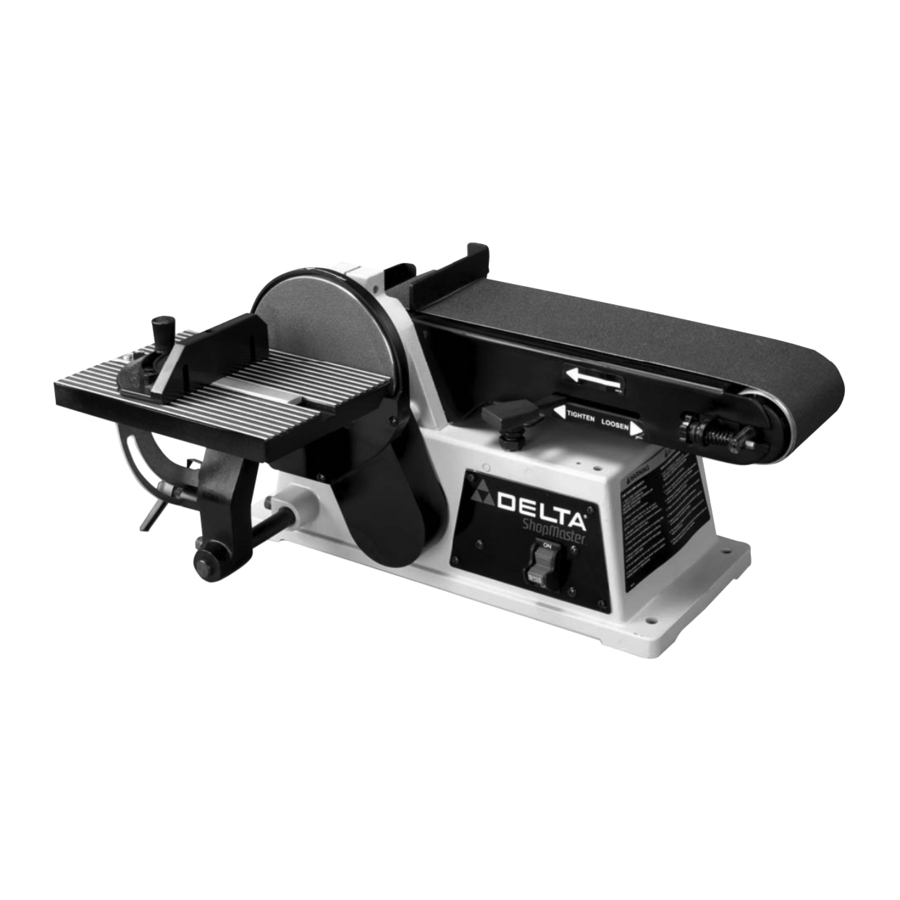
4" Belt / 6" Disc Sander
(Model SA446)
PART NO. 905578 -05-03-02
Copyright © 2002 Delta Machinery
To learn more about DELTA MACHINERY
ESPAÑOL: PÁGINA 21
visit our website at: www.deltamachinery.com.
For Parts, Service, Warranty or other Assistance,
1-800-223-7278 (
1-800-463-3582).
please call
In Canada call
Advertisement
Table of Contents

Related Manuals for Delta ShopMaster SA446


Summary of Contents for Delta ShopMaster SA446
- Page 1 4" Belt / 6" Disc Sander (Model SA446) PART NO. 905578 -05-03-02 Copyright © 2002 Delta Machinery To learn more about DELTA MACHINERY ESPAÑOL: PÁGINA 21 visit our website at: www.deltamachinery.com. For Parts, Service, Warranty or other Assistance, 1-800-223-7278 ( 1-800-463-3582).
-
Page 2: General Safety Rules
If you have any questions relative to a particular application, DO NOT use the machine until you have first contacted Delta to determine if it can or should be performed on the product. -
Page 3: Additional Safety Rules For Belt / Disc Sanders
Replace missing, damaged or failed parts before resuming operation. 27. THE USE of attachments and accessories not recommended by Delta may result in the risk of injuries. 28. ADDITIONAL INFORMATION regarding the safe and proper operation of this product is available from the... -
Page 4: Power Connections
A separate electrical circuit should be used for your machines. This circuit should not be less than #12 wire and should be protected with a 20 Amp time lag fuse. If an extension cord is used, use only 3-wire extension cords which have 3- prong grounding type plugs and matching receptacle which will accept the machine’s plug. -
Page 5: Extension Cords
FOREWORD The Delta ShopMaster Model SA446 is a 4" Belt; 6" Disc Sander and comes equipped with; 1/3 hp 120 Volt Single Phase Induction Motor, tilting table, miter gage, backstop, 4" x 36"- 60 grit sanding belt and 6"- 60 grit sanding disc. - Page 6 4" BELT / 6" DISC SANDER PARTS Fig. 1A Fig. 1A Sander Parts 1. Motor and Base 2. Disc Table 3. Belt and Pulley Guard 4. Disc Plate 5. Dust Chute 6. Support Rod 7. Lower Disc Guard 8. Sanding Disc 9.
-
Page 7: Adjusting Belt Tension
ASSEMBLY INSTRUCTIONS WARNING: FOR YOUR OWN SAFETY, DO NOT CONNECT THE SANDER TO THE POWER SOURCE UNTIL THE MACHINE IS COMPLETELY ASSEMBLED AND YOU READ AND UNDERSTAND THE ENTIRE OWNERS MANUAL. ADJUSTING BELT TENSION Your sander was shipped from the factory with the drive belt (A) Fig. -
Page 8: Assembling Belt And Pulley Guard
ASSEMBLING BELT AND PULLEY GUARD Assemble the belt and pulley guard (A) Fig. 5, to the machine base using the two M6x1x30mm cheese head screws (B), as shown. ASSEMBLING SANDING DISC PLATE Back the 1/4-20x1/4" hex socket set screw (A) Fig. 6, out of the hole, just enough so that the set screw is not extending into hole (B) Fig. -
Page 9: Assembling Lower Cover For Sanding Disc
DISC SANDER TABLE Thread a M8x1.25x20mm hex socket head screw (A) Fig. 11, part-way into threaded hole in base of sander and insert rod (B) into hole as shown. Align flat on rod (B) with screw (A) and tighten screw (A). -
Page 10: Fastening Sander To Supporting Surface
POSITIONED A MAXIMUM OF 1/16 INCH AWAY FROM SANDING BELT (E). FASTENING SANDER TO SUPPORTING SURFACE If your sander is to be used in a permanent location, it should be fastened securely to a firm supporting surface, such as a stand or workbench using the four holes, three of which are shown at (A) Fig. -
Page 11: Operating Controls And Adjustments
STARTING AND STOPPING SANDER The switch (A) Fig. 22, is located on the sander base. To turn the sander “ON” move the switch up to the “ON” position. To turn the sander “OFF” move the switch down to the “OFF” position. -
Page 12: Locking Switch In The "Off" Position
LOCKING SWITCH IN THE “OFF” POSITION IMPORTANT: When the machine is not in use, the switch should be locked in the “OFF” position to prevent unauthorized use. This can be done by grasping the switch toggle (B) Fig. 23, and pulling it out of the switch as shown. -
Page 13: Tilting The Table
ADJUSTING BACKSTOP SQUARE WITH SANDING BELT DISCONNECT MACHINE FROM POWER SOURCE. When making this adjustment make sure the belt tension lever (A) Fig. 28, is all the way to the left in the tightened position, as shown. Place a square (B) Fig. 29, on the sanding belt with one end of the square against the backstop, and check to see if the backstop is square with the sanding belt. -
Page 14: Miter Gage
ADJUSTING MITER GAGE SLOT PARALLEL WITH SANDING DISC DISCONNECT MACHINE FROM POWER SOURCE. Using a combination square (A) in the miter gage slot, check the distance from the slot to each end of the sanding disc, as shown in Figs. 32 and 33. This distance should be the same. -
Page 15: Dust Chute
THE WORK OR FINGERS BETWEEN THE TABLE AND SANDING BELT. DUST CHUTE A dust chute (A) Fig. 38, is supplied with your sander and can be connected to a standard shop vacuum hose. The outside diameter of the opening of the dust spout is 2- 1/2 inches. -
Page 16: Replacing Sanding Belt
Re-apply belt tension by sliding tension lever (C) Fig. 41, to the left. Replace backstop which was removed in STEP 2. Connect electrical power to the sander and check to see if the belt is tracking properly. If not, refer to the section “TRACKING THE SANDING BELT”. -
Page 17: Operation
Peel off old disc (E) as shown in Fig. 44. Make sure the disc plate (F) Fig. 44, is clean and peel backing from new sanding disc. Press the new sanding disc firmly into position on disc plate (F) and replace lower cover and table assembly which were removed in STEPS 2 and 3. -
Page 18: Sanding Outside Curves
SANDING INSIDE CURVES Inside curves can be sanded on the top sanding drum, as shown in Fig. 47. SANDING OUTSIDE CURVES Outside curves should be sanded on the sanding disc as shown in Fig. 48. WARNING: ALWAYS SAND ON THE LEFT (DOWNWARD) SIDE OF THE SANDING DISC, AS SHOWN. - Page 19 NOTES...
-
Page 20: Parts, Service Or Warranty Assistance
1-800-223-7278 (In Canada call 1-800-463-3582). Delta will repair or replace, at its expense and at its option, any Delta machine, machine part, or machine accessory which in normal use has proven to be defective in workmanship or material, provided that the customer returns the product prepaid to a Delta factory service center or authorized service station with proof of purchase of the product within two years and provides Delta with reasonable opportunity to verify the alleged defect by inspection.
Need help?
Do you have a question about the ShopMaster SA446 and is the answer not in the manual?
Questions and answers